YCP10 Users_E.pdf - 第282页
A-2 Appendix 1.1.2 Edge clamp air pressure T he edge clamp that pushes against the board edge to clamp it is actuated by compressed air . T his air pressure should be set to an optimum level (usually 0.225MP a). When nec…
A-1
Appendix
1. Specifications
1.1 Air regulator unit
1.1.1 Air supply
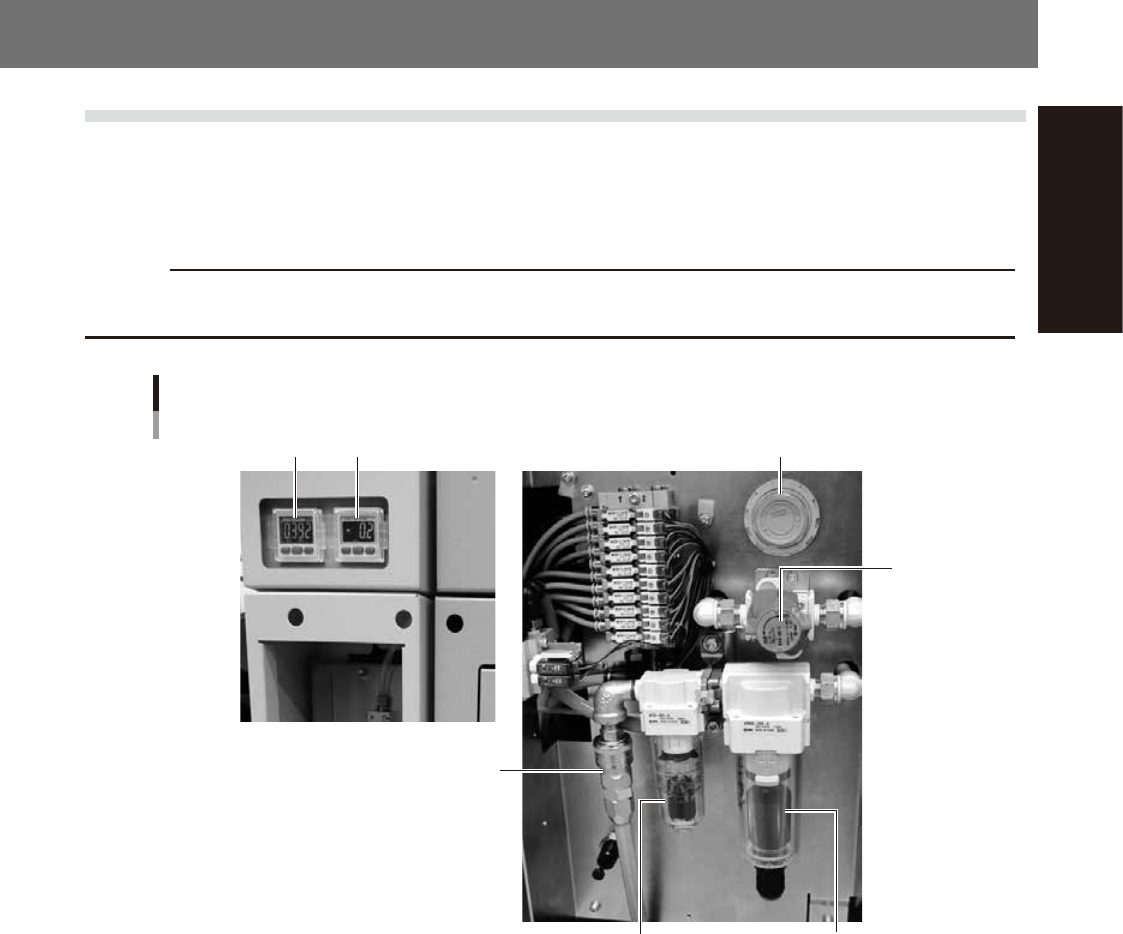
The air pressure regulator is located behind the front lower panel of the machine. The air pressure regulator
must be correctly set to supply the machine at an optimum air pressure.
c
CAUTION
Before setting the air pressure, make sure that the pressure from the primary air supply is within an appropriate range
(0.45MPa or less).
Air pressure regulator and air connector
Mist filter
4
31 2
5
Air filter
53A01-N1-00
1. Air pressure display
Shows the set air pressure. Use the pressure regulator knob to display the pressure levels described below.
• Set air pressure level: 0.40MPa to 0.41MPa
2 Pressure gauge (for cleaner suction)
Shows the cleaner's vacuum air pressure level (negative pressure level).
3. Supply air pressure regulator valve knob
Use this knob to adjust the supply air pressure to a proper set pressure level.
Turn the knob to adjust the supply air pressure so that the set air pressure level shows “0.40MPa”.
4. Air pressure supply/shutoff switch
Turning this switch to the right shuts off air supply and exhausts air that remains inside the machine.
5. Source air connector
Prepare an air hose with an inner diameter of at least 8 mm having a 30SH socket (Nitto Koki, or equivalent), and
connect it to this connector. Use dry, clean air passed through an air filter.
A-2
Appendix
1.1.2 Edge clamp air pressure
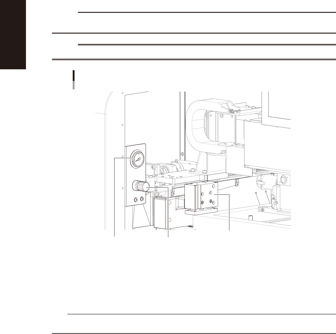
The edge clamp that pushes against the board edge to clamp it is actuated by compressed air. This air pressure should be
set to an optimum level (usually 0.225MPa). When necessary, turn the knob on the pressure regulator on the left side
inside the main unit to adjust the air pressure.
c
CAUTION
Before adjusting the edge clamp air pressure, make sure that the air pressure in the machine is set to the optimum
level (0.40 to 0.41MPa).
w
WARNING
BEFORE ADJUSTING THE EDGE CLAMP AIR PRESSURE, BE SURE THAT THE MACHINE IS IN EMERGENCY STOP.
Adjusting the edge clamp air pressure
Left side inside the main unit
Pressure regulator
Pressure gauge
(Set to 0.225MPa in most cases.)
Mask clamp
53A02-N1-00
Pressure gauge (for edge clamp)
Shows the edge clamp air pressure.
Pressure regulator
Adjusts the air pressure to be supplied to the edge clamp.
n
NOTE
If multi-board panels or thin boards warp up when force is applied by the edge clamp, reduce the edge clamp air
pressure. Conversely, if you want to clamp heavy boards more securely, increase the air pressure.
A-3
Appendix
1.2 Power connection terminals
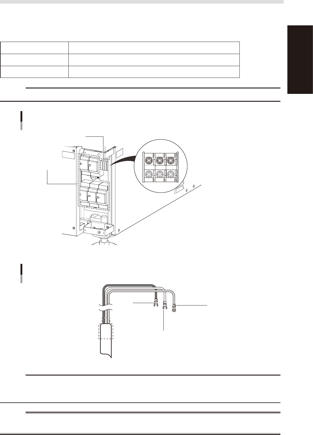
When opening the panel at the lower portion on the front of the main unit, you can see the power connection
terminals. Use the power cable shown in the figure below to connect the power cable leads to the primary
terminals L1 and L2 on the main breaker and the ground terminal on the main unit chassis.
n
Power supply specifications
Power Single-phase AC 200 / 208/ 220 / 230V ±20V
Frequency 50/60Hz
Power capacity 6.9KVA (excluding optional air conditioner)
c
CAUTION
When installing an earth leakage breaker on the host unit, its sensitivity current must be 30mA or more.
Power input terminal
Power input terminal M5
Terminal blocks
Main breaker
L1 L2 PE
53A03-N1-10
Connecting power cables (example)
L1
L M5
L2
N M5
Ground (green)
L = 350 mm
Crimp ring terminal M5
53A04-N1-10
c
CAUTION
Use a power cable with a grade of cross-sectional area of the conductor is 6.0 mm2 or more.
Make sure that the power cable connections are correct. If misconnected, the vacuum operation of the suction unit
will be reversed (air blows outward).
w
WARNING
TO AVOID THE RISK OF ELECTRICAL SHOCK, MAKE SURE THAT THE POWER SOURCE IS OFF BEFORE CONNECTING THE
POWER CABLE. ALSO MAKE SURE THAT THE GROUND CABLE IS SECURELY CONNECTED TO THE MACHINE.