YCP10 Users_E.pdf - 第265页
2-18 2 Inspection and maintenance 3.3.2 Replacing the blower hose T o replace the blower hose, follow the steps below . n Required tools • Slotted screwdriver • Replacement blower hose (KL V -M37D9-0XX TUBE 25) e 1 Perfo…
2-17
2
Inspection and maintenance
3.3 Suction-blower unit
The suction-blower unit is always operated even when the machine is in emergency stop. It is therefore
necessary to clean and replace the filter and replace the blower hose periodically.
3.3.1 Replacing the filter
To clean and replace the filter, follow the steps below.
n
Required tools
• Phillips screwdriver
• Replacement filter (KGY-M3710-4XX INL FILTER ELEMENT)
• Air blow tool (option)
1
Move the printing table and
cleaning unit.
Open the [Setup] tab on the Setup screen
and press the [Manual Cleaning] button.
The printing table is then connected to the
cleaning unit and they move backward.
e
2
After pressing the emergency stop
button, open the upper door and
front panel.
To ensure the work safety, be sure to put the
machine in the emergency stop state.
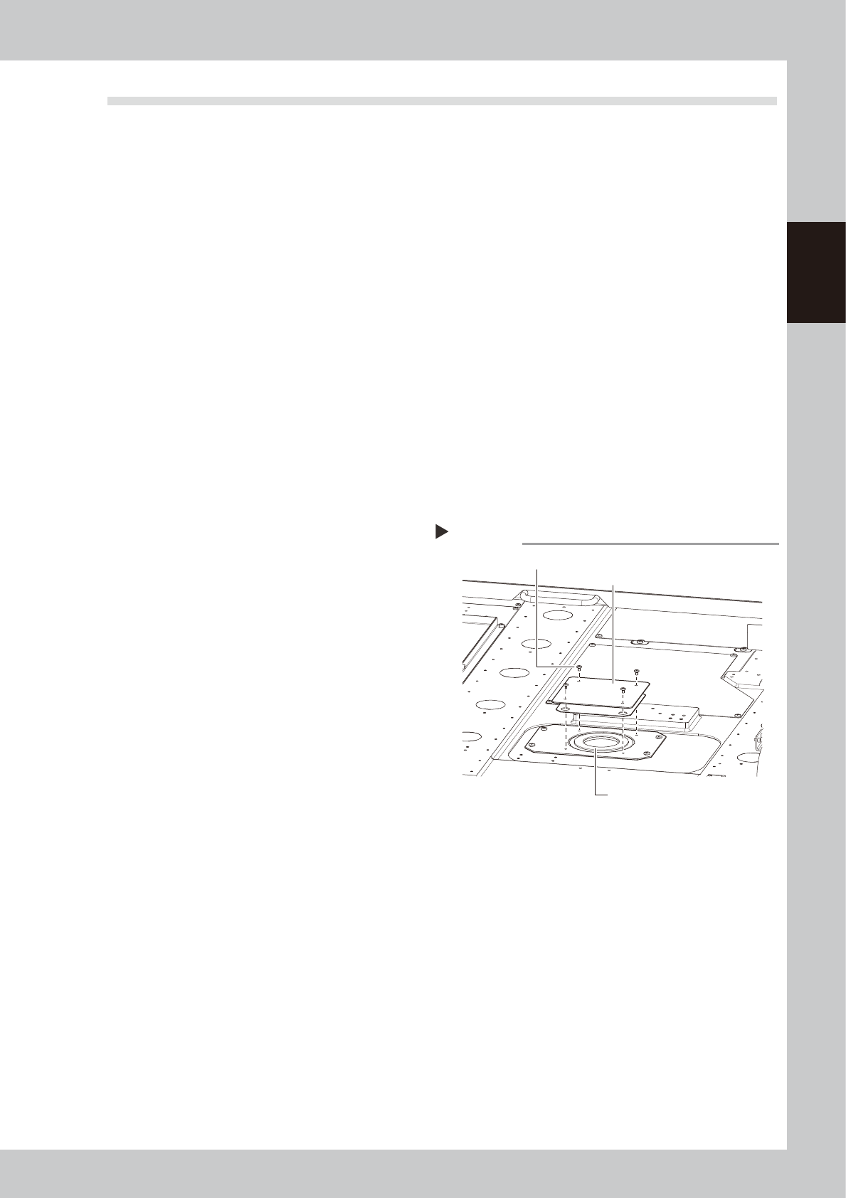
3
Remove the filter cover.
Use a Phillips screwdriver to remove 4
mounting screws and detach the cover.
53210-N1-00
4
Take out the filter and clean it.
Take out the ring-shape filter and blow it
from the outside and inside using an air blow
tool.
If the filter is contaminated significantly,
replace it with a new one.
5
Return the filter to its original
position.
Insert the filter to its original position and
close the cover.
6
Release the connection between
the printing table and cleaning
unit.
Open the [Unit]-[Cleaner] tab and press the
[Cleaner Connect] button to release the
connection.
The cleaning unit will return to its original
position, and it is then secured.
Removing the filter cover
Step 3
Mounting screws (4 places)
Filter
Filter cover
2-18
2
Inspection and maintenance
3.3.2 Replacing the blower hose
To replace the blower hose, follow the steps below.
n
Required tools
• Slotted screwdriver
• Replacement blower hose (KLV-M37D9-0XX TUBE 25)
e
1
Perform the return-to-origin.
After checking the safety, press the [Origin]
button on the Setup screen. The printing
table will move toward the rear.
2
Press the emergency stop button
and open the upper door and front
panel.
To ensure the work safety, be sure to put the
machine in the emergency stop state.
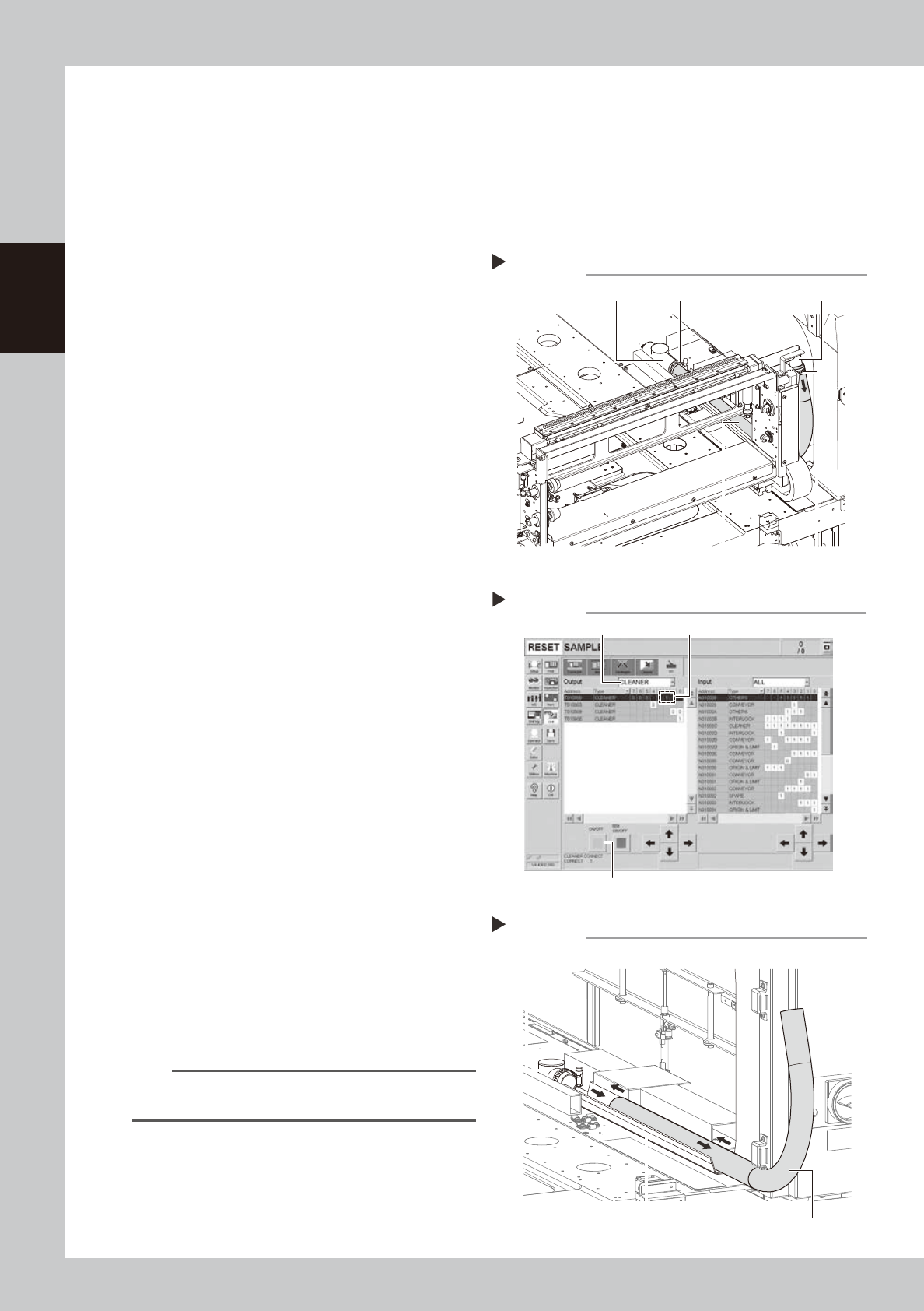
3
Disconnect the blower hose on the
cleaning unit side.
Use a flat-blade screwdriver to loosen the
hose band and disconnect the blower hose
from the joint.
53211-N1-00
4
Move the cleaning unit to the rear.
1. Open the [Unit]-[I/O] tab and select
“CLEANER” from the “Output” drop-down
list.
2. Select “T0100002” (cleaner connection)
and press the [ON/OFF] button to set "1"
(connection). The cleaning unit clamp is
then released.
3. Move the cleaning unit to the rear by
hand.
54201-N1-00
5
Disconnect the blower hose on the
base side.
1. Move the squeegee head to the rear.
2. Disconnect the blower hose from the
vacuum pipe.
6
Replace the blower hose.
Pull out the old blower hose toward you from
the cleaning unit side.
Insert a new blower hose along the hose
guide.
53212-N1-00
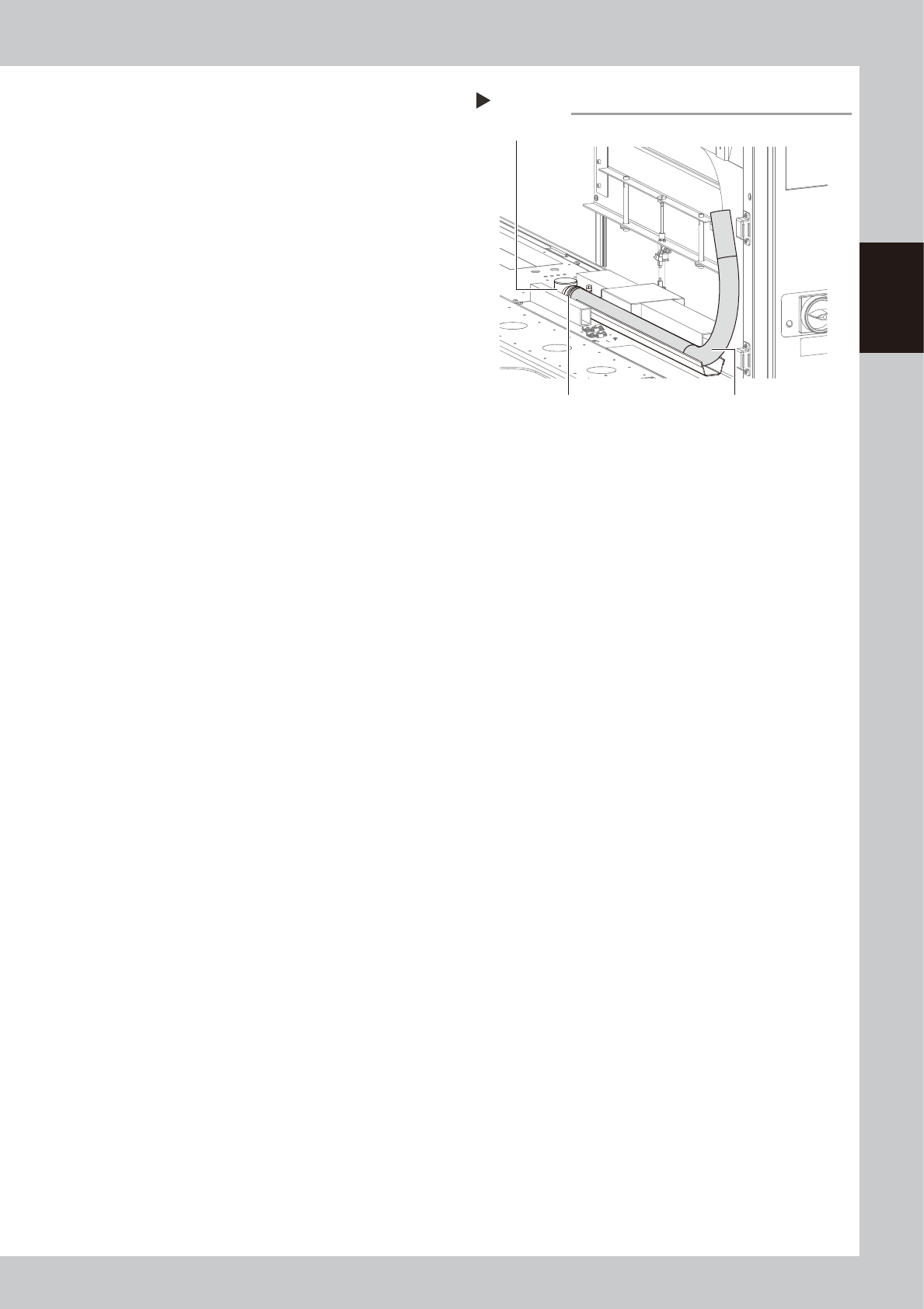
n
NOTE
Insert the blower hose so that it smoothly bends
upward.
Removing the blower hose
Step 3
Hose band
Hose band JointVacuum pipe
Blower hose
[Unit]-[I/O] tab screen
Step 4
Select “CLEANER”.
Select “T0100002”.
[ON/OFF] button
Replacing the blower hose
Step 6
Hose guide Blower hose
Vacuum pipe
2-19
2
Inspection and maintenance
7
Connect the blower hose on the
base side to the vacuum pipe
temporarily.
Connect the blower hose to the vacuum
pipe temporarily.
53216-N1-00
8
Connect the blower hose on the
cleaning unit to the vacuum pipe.
1. Move the cleaning unit to the front by
hand.
2. Connect the blower hose to the joint and
tighten the hose band with a flat-blade
screwdriver to secure it.
9
Check the blower hose position
from the cleaning unit side.
Move the cleaning unit to the rear by hand.
Check that the blower hose is stored straight
above the hose guide.
0
Secure the blower hose.
Tighten the hose band of the vacuum pipe
on the base side with a flat-blade
screwdriver, and then secure it.
q
Return the cleaning unit to its
original position.
1. Return the cleaner head that has been
moved to the rear in Step 9 to its original
position.
2. Open the [Unit]-[I/O] tab and select
“CLEANER” from the “Output” drop-down
list.
3. Select “T0100002” (cleaner connection)
and press the [ON/OFF] button to set "0"
(release).
The cleaning unit is then secured.
Connecting the blower hose
Step 7
Blower hose
Vacuum pipe
Hose band