YCP10 Users_E.pdf - 第41页
Chapter 1 Par t names and functions T his chapter explains YCP10 major part names and functions. Make sure that you understand the location and function of eac h part before attempting machine operation. Contents 1. YCP1…
iii
About this manual
1.3 Page layout
The description below shows a typical page layout used in this manual.
Typical page layout
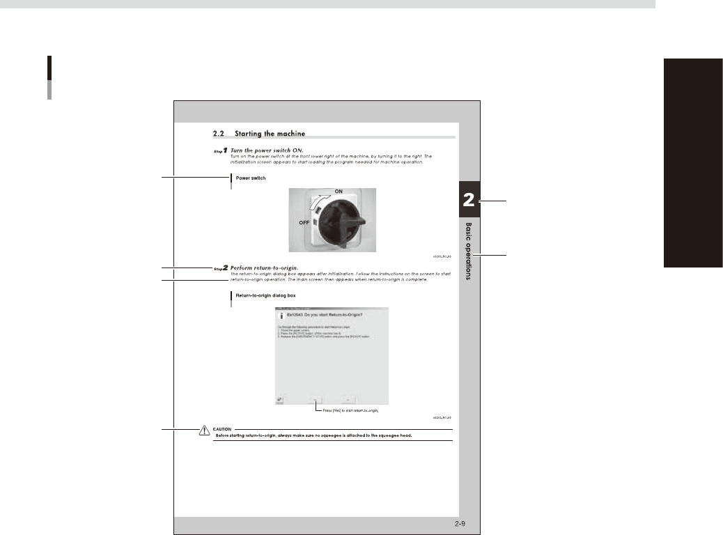
Step
Chapter number
Chapter title
Sub step or description
of step
Figure, picture or table
caption
Note, Caution or Warning
63001-N1-00
n
Step
This describes the procedure for each operation.
n
Substep or description of step
This provides detailed information on the steps in each procedure.
n
Illustration or table caption
This is the title of the illustration or table and appears at the upper left.
n
Note, Caution or Warning
These are explained in detail in "Safety instructions".

Chapter 1 Part names and functions
This chapter explains YCP10 major part names and functions. Make sure that you understand the location and function of each
part before attempting machine operation.
Contents
1. YCP10 main unit 1-1
2. Operation panels and data input units 1-4
2.1 Operation panel buttons 1-5
2.2 Operation display screen 1-6
2.3 Keyboard (option) 1-6
3. Printing section 1-7
3.1 Squeegee head and printing table 1-7
3.2 3S squeegee 1-8
3.3 Double squeegee (option) 1-9
4. Conveyor unit 1-10
4.1 Board clamp unit (board clamp table) 1-10
4.2 Board support 1-11
5. Cleaning unit 1-15
5.1 Cleaning unit 1-15
5.2 Suction unit 1-16
6. Vision camera unit 1-17
7. Servo-controlled axes 1-18
1-1
1
Part names and functions
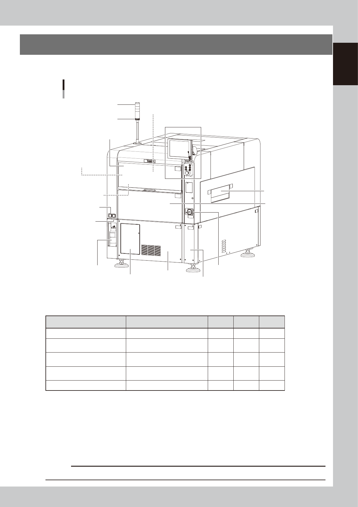
1. YCP10 main unit
A standard machine has the following configurations after installation. Names and functions of major parts
of the main unit are described on the subsequent pages.
YCP10 main unit
Front view
Pressure regulator
for edge clamp
Pressure gauge
Panel door at lower portion on front
Right panel at lower portion on front
Solvent bottle
Signal light
Buzzer
Printing section
(Squeegee head, printing table)
Operation panel and data input unit
Upper door (safety cover)
Conveyor unit
(below printing table)
Pressure gauge
Cleaner vaccum
pressure gauge
Front lower panel
Power switch
Front panel
Safety shutter
63101-N1-10
n
Signal light
Indicates current operating conditions of the mounter with a green, yellow and red light, or green, white and blue light
explained below. (The colors of the signal light can be selected from two patterns.)
Machine status Example Green
Red/
White
Yellow/
Blue
Warm-up or automatic operation ON ----- -----
Emergency stopper safety cover
switch activated
----- ON -----
System error
(with buzzer ON)
• Excessive current
• Secondary limit is exceeded
----- ON -----
Operation or board data error
(with buzzer ON)
• Error stop
• Stopped by interlock device
----- ----- ON
Materials cannot be used. Solder ----- ----- ON
n
Alarm buzzer
This buzzer sounds if an error or abnormal operation occurs. (The color of the signal light when a buzzer sounds can be
selected from two patterns (option). (The buzzer volume can be adjusted by turning the buzzer ring right or left.)
n
Upper door (safety cover)
This cover must be kept closed during operation. If opened, emergency stop is triggered.
n
Power switch
Turns the power to the machine on and off. The power is on when turned to the right.
c
CAUTION
Wait about 2 seconds before turning the power switch back on after having turned it off.