YCP10 Users_E.pdf - 第73页
2-13 2 Basic operations 3. Operation screen description The basic configuration and operation methods of the software screens are explained in this section. Please read through this section before operating the machine. …

2-12
2
Basic operations
4
Press [Yes] button when the "SHUT DOWN" screen appears.
The application software automatically closes.
e
5
Press the emergency stop button.
When the "emergency stop" screen appears, press the emergency stop button and then press the [OK]
button.
6
Turn off the machine power switch.
When the message to power off the machine, "It is now safe to turn off your computer" appears, turn
counterclockwise the power switch on the machine to power off the machine.
c
CAUTION
Data or machine might be damaged or lost if powering off the machine without following the above sequence.
c
CAUTION
To start the machine again after powering off the machine, wait for 2 sec. or longer and power on the machine. If you
ignore this instruction, a trouble may occur when starting the machine again.
2-13
2
Basic operations
3. Operation screen description
The basic configuration and operation methods of the software screens are explained in this section.
Please read through this section before operating the machine.
n
NOTE
As standard specification systems have no keyboard or mouse, all operations are performed from the touch-panel. A
screen appears at parameter input operations, and the desired operations and inputs can then be performed with
the touch-pen.
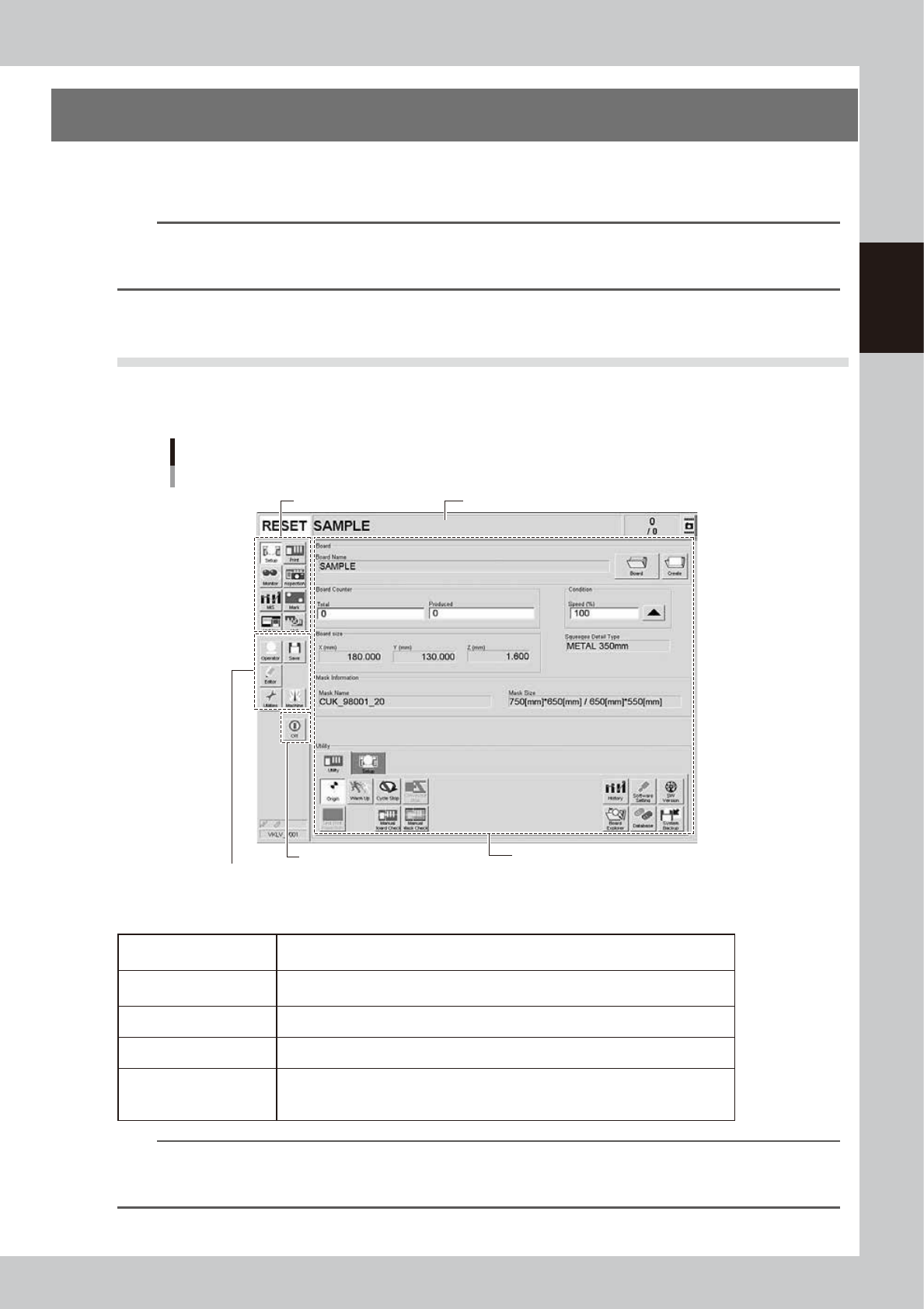
3.1 Basic configuration of operation screen
The operation screen can be divided into the "Status", "Main menu button" and "Submenu button and
parameter" areas as shown below.
Operation screen basic elements
Setup screen (after selecting board data)
Submenu button
and parameter area
Main menu button area 1
Main menu button area 3
Main menu button area 2
Status area
64207-N1-10
n
Description of each area
Status area
Displays the current machine status on the left end, the selected board data name
in the middle and the number of boards that were produced on the right end.
Main menu button area 1
Shows the main menu buttons used to operate the machine. The submenu button
and parameter area will change according to the selected main menu button.
Main menu button area 2 Shows the menu buttons used to call up auxiliary functions.
Main menu button area 3 Shows the [Off] button to power off the machine power.
Submenu button and
parameter area
Displays the submenu buttons and parameters for machine operation and data
setting.
This area will change according to the selected main menu button.
TIP
The submenu button and parameter area will change according to the selected main menu button. For details on
the menu button functions and parameter items on the operation monitor, see "Chapter 4 Daily operation" to
"Chapter 7 Other functions" in this manual.
2-14
2
Basic operations
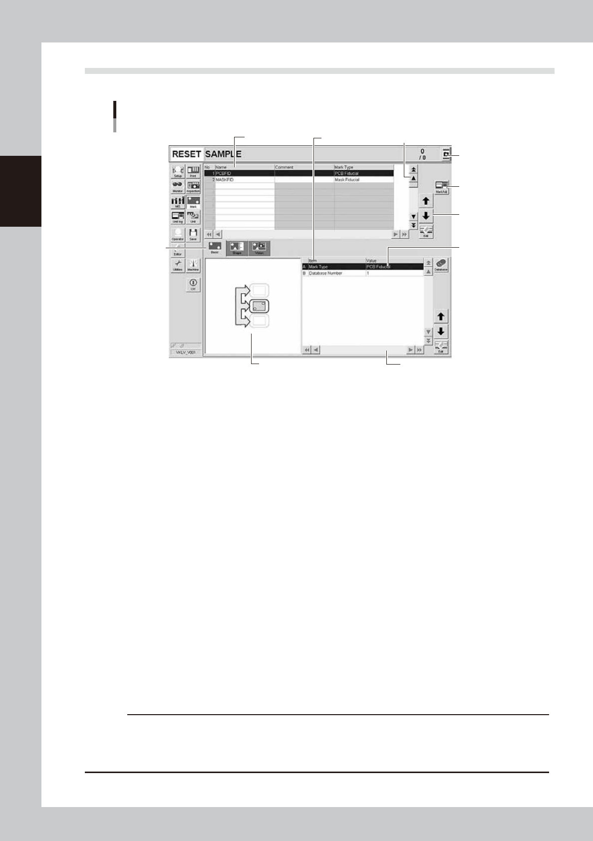
3.2 Various buttons and parameter input grids
Various types of buttons, selection tabs and parameter input grids are used on the operation screen.
Operation screen basic elements
Mark screen
Data No. list
1
1
2
3
4
5
6
7
Parameter list
64208-N1-20
1. Scroll bar and button (up/down, left/right)
Use the scroll bars or arrow buttons to see hidden items in the data No. list or parameter list.
2. Operation button
Press these buttons to open the next operation screen.
3. Line up/down button
Use these buttons to move the cursor up or down through the data No. list or parameter list.
4. Parameter input box
Select, enter or edit parameters here. When the keyboard is used, double-click on a parameter input box to enter or edit
the data.
When a touch screen (option) is used, press the [Edit] button on the lower right of the parameter list. The edit box then
pops up for data input and editing.
5. Selection tab
Select this tab to switch the parameter input screen.
6. Assistant screen
Shows an illustration or information useful for parameter input or editing.
Alphabet characters shown in the parameter list and in the illustration on this screen correspond to each other.
7. Capture button
Captures the displayed image. The captured data (JPEG format) is stored in the D:\ScreenShot folder (maximum folder
size: approx. 10MB), with a file name consisting of the date and time.
When a USB flash drive is inserted into the machine’s USB port and system backup is performed, a “ScreenShot” folder is
created in the root of the USB flash drive to acquire the captured data stored in the machine. (The captured data stored
in the machine is moved to the USB flash drive.)
c
CAUTION
• When saving data in a USB flash drive, make sure to use the USB flash drive designated by YAMAHA.
• If you specify the destination to save the data on the “Screen Shot Setting” window (Press the [Setup] – [Software
Setting] – [Information] – [Screen Shot Setting] buttons), the captured data cannot be saved in the USB flash
drive even by performing System backup.