YCP10 Users_E.pdf - 第75页
Chapter 3 Printing guide T his chapter explains data setting and changeov er tasks to perform satisfactory solder printing. T his chapter also describes the relation between the print trouble symptoms and the conditions …
2-14
2
Basic operations
3.2 Various buttons and parameter input grids
Various types of buttons, selection tabs and parameter input grids are used on the operation screen.
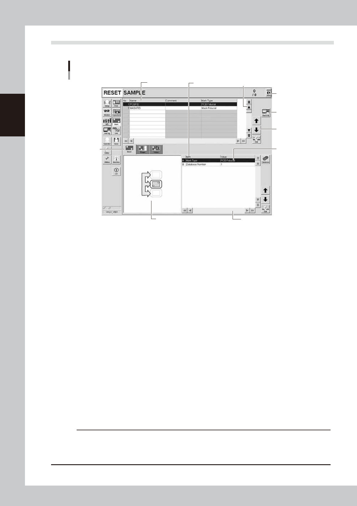
Operation screen basic elements
Mark screen
Data No. list
1
1
2
3
4
5
6
7
Parameter list
64208-N1-20
1. Scroll bar and button (up/down, left/right)
Use the scroll bars or arrow buttons to see hidden items in the data No. list or parameter list.
2. Operation button
Press these buttons to open the next operation screen.
3. Line up/down button
Use these buttons to move the cursor up or down through the data No. list or parameter list.
4. Parameter input box
Select, enter or edit parameters here. When the keyboard is used, double-click on a parameter input box to enter or edit
the data.
When a touch screen (option) is used, press the [Edit] button on the lower right of the parameter list. The edit box then
pops up for data input and editing.
5. Selection tab
Select this tab to switch the parameter input screen.
6. Assistant screen
Shows an illustration or information useful for parameter input or editing.
Alphabet characters shown in the parameter list and in the illustration on this screen correspond to each other.
7. Capture button
Captures the displayed image. The captured data (JPEG format) is stored in the D:\ScreenShot folder (maximum folder
size: approx. 10MB), with a file name consisting of the date and time.
When a USB flash drive is inserted into the machine’s USB port and system backup is performed, a “ScreenShot” folder is
created in the root of the USB flash drive to acquire the captured data stored in the machine. (The captured data stored
in the machine is moved to the USB flash drive.)
c
CAUTION
• When saving data in a USB flash drive, make sure to use the USB flash drive designated by YAMAHA.
• If you specify the destination to save the data on the “Screen Shot Setting” window (Press the [Setup] – [Software
Setting] – [Information] – [Screen Shot Setting] buttons), the captured data cannot be saved in the USB flash
drive even by performing System backup.

Chapter 3 Printing guide
This chapter explains data setting and changeover tasks to perform satisfactory solder printing. This chapter also describes the
relation between the print trouble symptoms and the conditions that may cause the trouble.
Before starting operation described in Chapter 4, “Daily operation”, read this chapter carefully.
Contents
1. Flow of printing condition setting 3-1
2. Data and condition setting 3-2
2.1 Material and setup information 3-2
2.2 Alignment offset setting 3-4
2.3 Rolling 3-5
2.4 Printing and production conditions 3-6
3. Details of each parameter item 3-7
3.1 Board clamp 3-7
3.1.1 Edge clamp pressure 3-7
3.1.2 Backup jig 3-7
3.2 Board transfer 3-8
3.2.1 Transfer position check 3-8
3.2.2 Board edge offset 3-9
3.2.3 Conveyor motor (board transfer) speed 3-11
3.2.4 X-axis movement during board transfer 3-12
3.2.5 Transfer start height 3-13
3.3 Board and mask mark recognition (Mark position) 3-14
3.4 Alignment offset 3-14
3.5 Squeegee (Rolling) 3-15
3.5.1 Squeegee speed 3-15
3.5.2 Squeegee pressure 3-15
3.5.3 Attack angle (degree (°)) 3-15
3.6 Solder supply interval 3-16
3.7 Detach pattern 3-16
3.7.1 Board separation speed 3-16
3.7.2 Board separation distance 3-17
3.8 Cleaning 3-17
3.8.1 Cleaning interval 3-17
3.8.2 Cleaning repeat 3-17
3.8.3 Cleaning speed 3-17