YCP10 Users_E.pdf - 第44页
1-3 1 Part names and functions n Main pressure regulator , air pressure supply/shutoff switch Regulates the air pressure supplied to the machine. n Right panel at lower portion on front Circuit breaker for each unit and …
1-2
1
Part names and functions
n
Pressure regulator for edge clamp, pressure gauge (left side inside main unit)
Shows or regulates the air pressure supplied to the edge clamp. For details, see Appendix 1.1.2, "Air pressure for edge
clamp".
n
Safety shutter
Safety shutter prevents hand from inserting into the machine during the operation. It also prevents a board from being
inserted incorrectly.
n
Conveyor unit
The conveyor unit is located under the printing table. For details, see "4. Conveyor unit" in this chapter.
n
Printing section
Consists of a printing table and a squeegee head. See "3. Printing section" later in this chapter for more details.
n
Main pressure gauge
Shows the air pressure supplied to the machine. For details, see Appendix 1.1, "Air pressure adjustment section".
n
Cleaner negative pressure gauge
Shows the negative pressure for the cleaner.
n
Front panel
Cleaning unit, conveyor unit, and vision camera unit are incorporated into the inside of the front panel. For details, see
"4. Conveyor unit", "5. Cleaning unit", and "6. Vision camera unit" in this Chapter.
n
Cleaning unit (inside front panel), cleaning solvent bottle (lower left portion on front)
Wipes away solder sticking to the print mask with a gauze roll. For details, see "5. Cleaning unit" in this Chapter.
n
Suction unit (inside front panel)
This unit sucks up solder adhering to the backside of the mask (stencil). See "5.2 Suction unit" in this chapter for more
details.
n
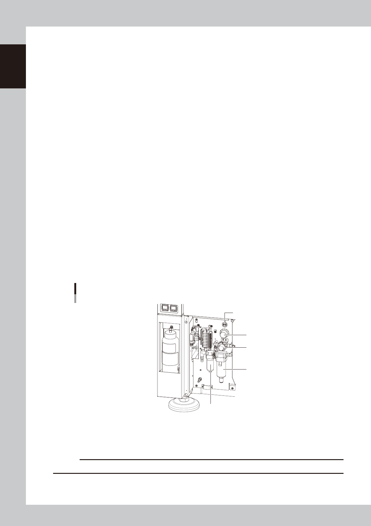
Front lower panel, panel door at lower portion on front
Inverter and suction blower unit are located on the right inside the panel.
When opening the door, main air pressure regulator, air pressure supply/shutoff switch, USB port, oil mist filter, and air
mist filter can be seen. Be sure to close the door during operation.
Air supply/shut-off switch
Oil mist filter
Air mist filter
Main air pressure regulator
USB port
Inside panel door at lower portion
63118-N1-00
n
USB port (front lower panel, inside door)
Connect to this port when using a USB flash drive to back up board data stored in the machine. Always close this media
access door before operating a USB flash drive.
c
CAUTION
Do not connect USB flash drive to USB port on optional keyboard.
1-3
1
Part names and functions
n
Main pressure regulator, air pressure supply/shutoff switch
Regulates the air pressure supplied to the machine.
n
Right panel at lower portion on front
Circuit breaker for each unit and power connection terminal are located inside the panel.
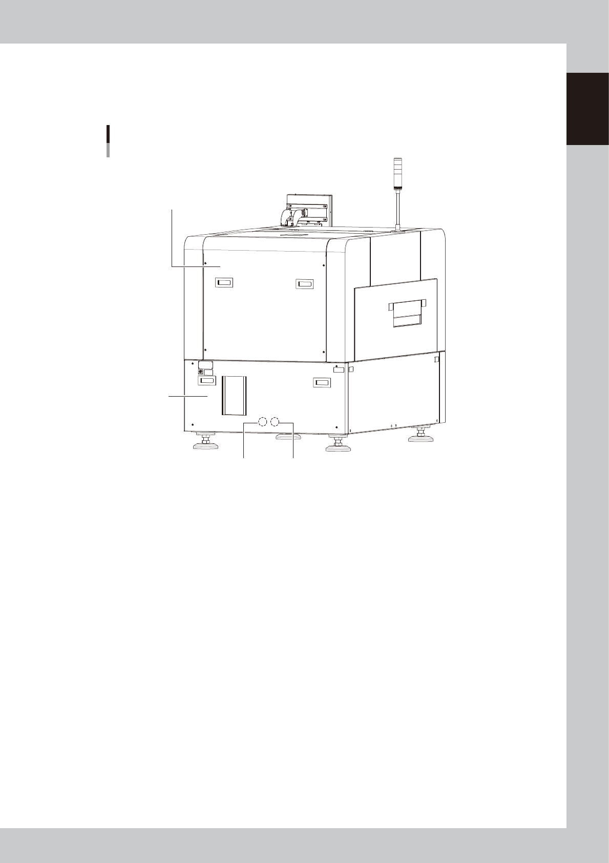
YCP 10main unit
Rear view
Previous Interface Next Interface
Rear lower panel
Rear cover
63102-N1-00
n
Rear cover
Be sure to close the cover during operation.
n
Rear lower panel
System motherboard, power supply board, servo control board, and vision board are assembled inside the panel.
n
I/O signal connectors (behind rear lower panel)
This connector is intended to connect the upstream machine and downstream machine. For details, see Appendix 1.3,
"Input/output connector between machines".
1-4
1
Part names and functions
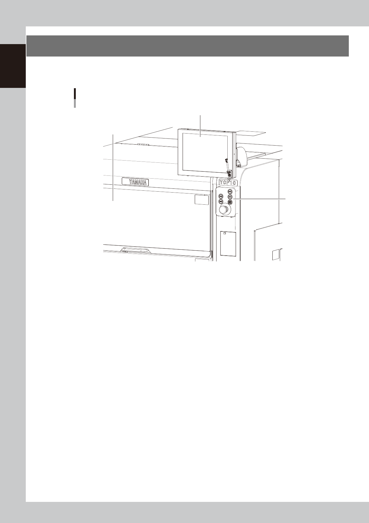
2. Operation panels and data input units
Operation panel buttons and operation display used to operate this machine or input the data are installed.
This section describes the functions of these units.
Operation panel and data input unit
Operation panel
buttons
Operation display
Upper door (safety cover)
63103-N1-00