YCP10 Users_E.pdf - 第82页
3-6 3 Printing guide 2.4 Printing and production conditions Printing and production conditions Step 1 Step 2 Step 3 64303-N1-10 1 Start the test print. 1. Press the [T est Print] button. Follow the messages that appear o…
3-5
3
Printing guide
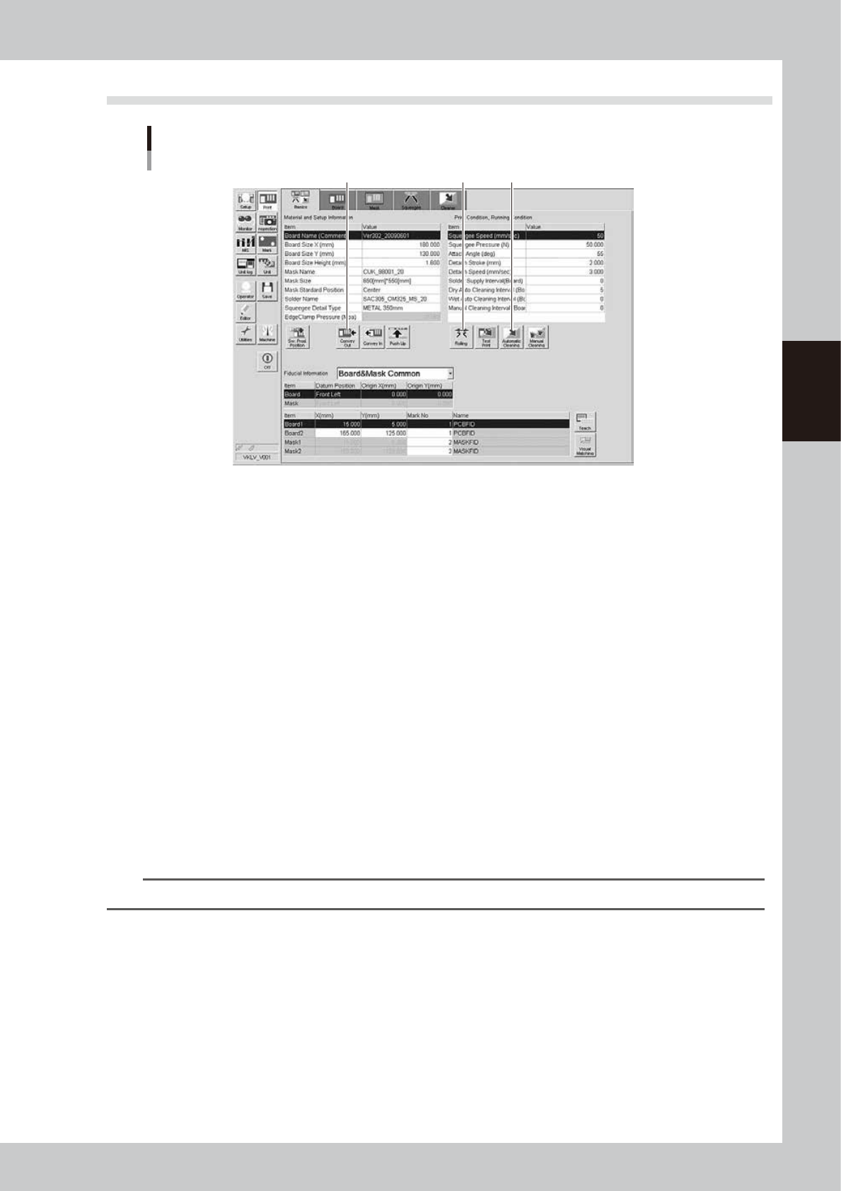
2.3 Rolling
Rolling
Step 4Step 2Step 5
64302-N1-10
1
Set the squeegee to be used.
2
Start the rolling operation.
1. Press the [Rolling] button, and follow the messages that appear on the operation screen to align the
board and mask positions. After the positions have been aligned completely, supply the solder. The
reference solder supply volume is one pod for a squeegee size of 530 mm. Based on this reference
volume, finely adjust the solder supply volume in accordance with the squeegee size.
2. Start the rolling. At this time, the squeegee pressure, squeegee speed, and attack angle are left set
at their default values.
3
Visually check the rolling condition.
l
If the solder slips:
If the rolling is not performed correctly due to solder slippage, decrease the squeegee speed.
l
If the scraped solder remains on the mask apertures:
Increase the printing pressure level or decrease the squeegee speed.
When no problem is found in the rolling and solder scraping condition, end the rolling operation.
4
Clean the mask by following the message on the screen.
Select the cleaning method “Dry”, “Wet” or "Controlled in the Board 1 to 4 tabs" and press the [OK]
button. The "Controlled in the Board 1 to 4 tabs" appears by selecting "Print" - "Cleaner" tab - "Detail
Setting" button.
TIP
See "6. Cleaner data setting" in Chapter 5 for "Controlled in the Board 1 to 4 tabs".
5
Unload the board by following the message on the screen.
3-6
3
Printing guide
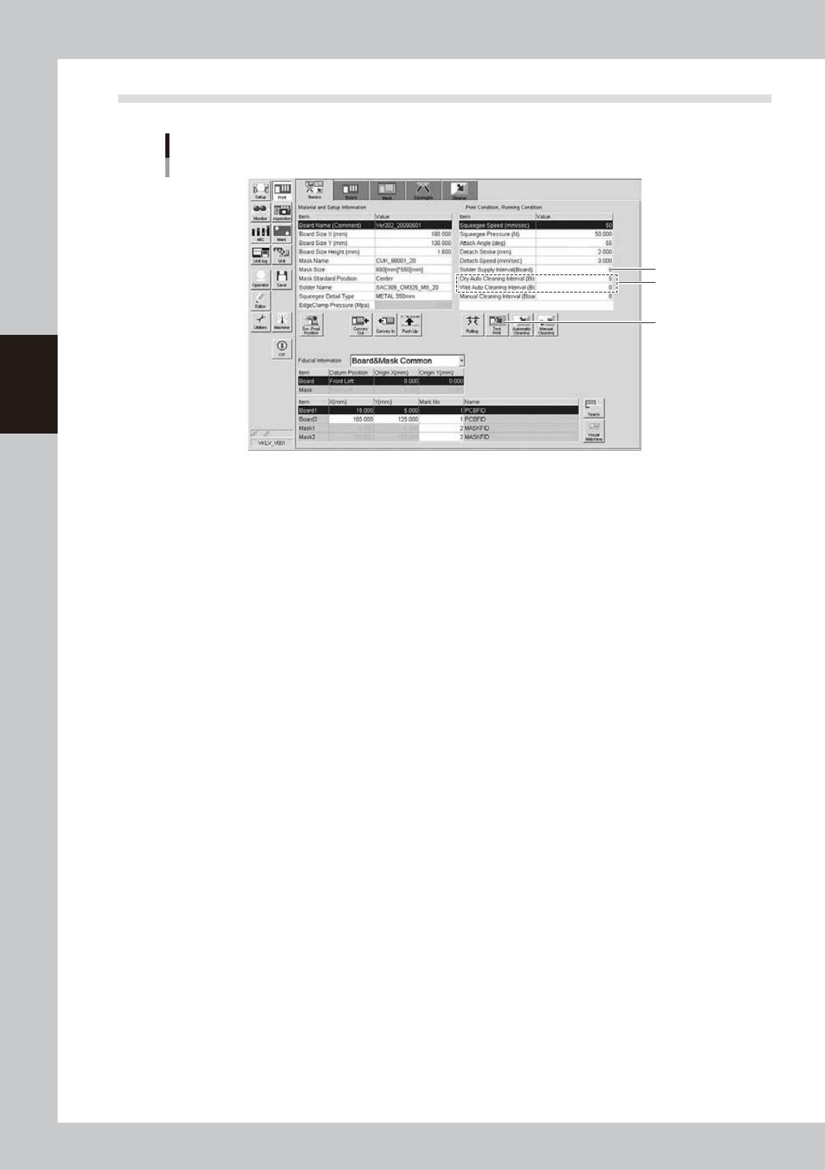
2.4 Printing and production conditions
Printing and production conditions
Step 1
Step 2
Step 3
64303-N1-10
1
Start the test print.
1. Press the [Test Print] button. Follow the messages that appear on the operation screen to load a
board, perform the printing, and unload the board.
2. Visually check the printed board.
3. If any print trouble is found, change relevant conditions by referring to "4. Causes of troubles by
symptoms" in this chapter.
4. Start the test print again with the condition data you have changed.
2
Set cleaning conditions.
1. Enter a numeric value in the [Cleaning Interval] field. At this time, when the value is set at “0”, the
cleaning is not performed.
2. Start the cleaning with the cleaning speed and cleaning repeat set at their initial values. If you want
to change the value in the [Cleaning Speed] or [Cleaning Repeat] field, set the value on the
[Cleaner] tab screen.
Enter values as described above and start the production. If any print trouble caused by cleaning
occurs, change the values appropriately.
3
Set a solder supply interval.
Set how many boards are printed by one solder supply operation.
Normally, enter the number of boards that may consume 10 to 20% of the solder supply volume.
3-7
3
Printing guide
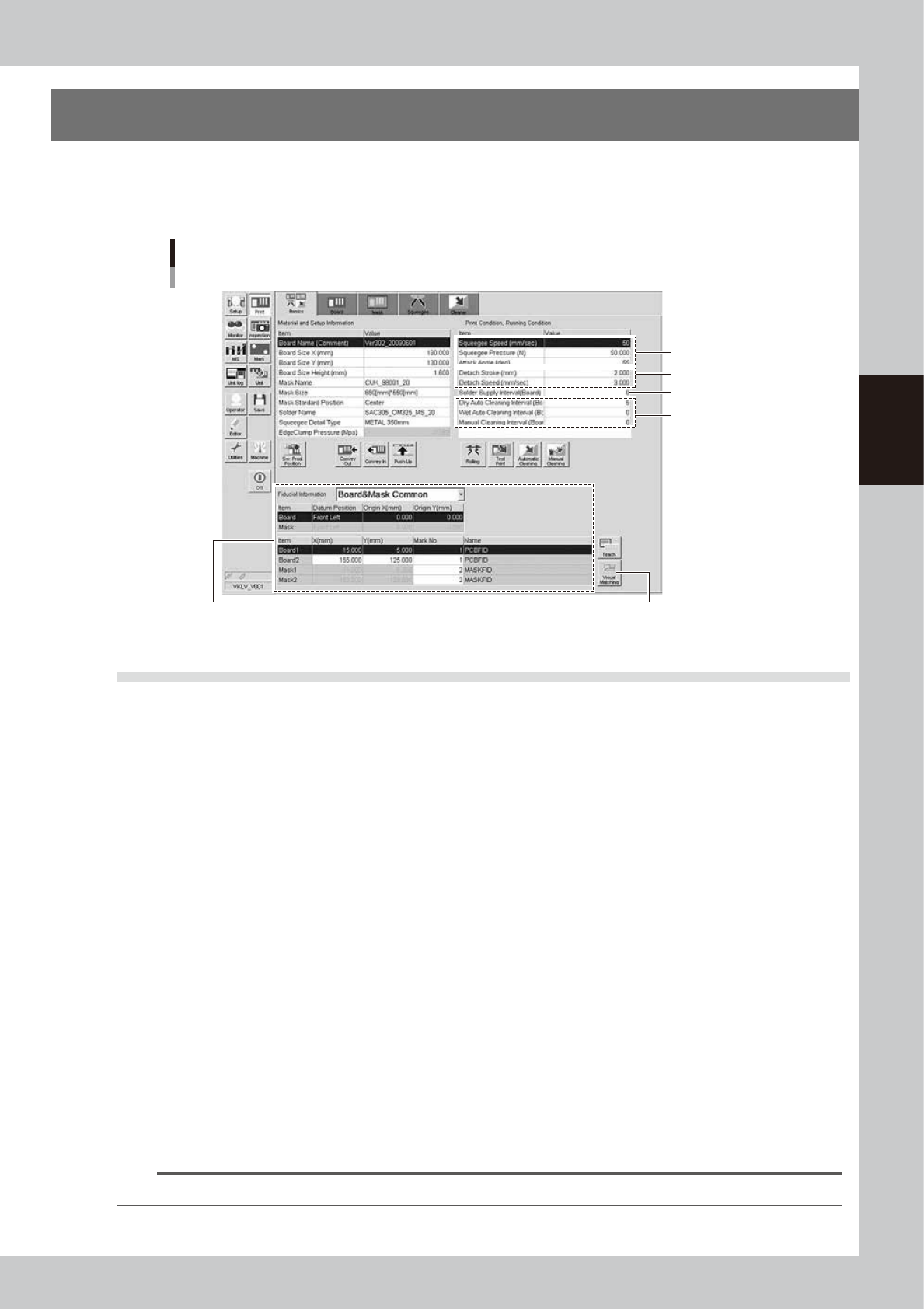
3. Details of each parameter item
To continuously perform the production with excellent printing quality, it is absolutely required to properly set
conditions for each solder paste printer as described previously.
The following describes how the conditions for each operation affect the printing quality.
Each parameter item
3.3 Mark position 3.4 Alignment offset
3.5 Rolling
3.7 Detach pattern
3.8.1
Cleaning interval
3.6 Solder supply interval
64304-N1-10
3.1 Board clamp
3.1.1 Edge clamp pressure
n
Function
This parameter sets a level of the air pressure supplied to the cylinder which is used to catch a board and clamp it.
n
Setting range and initial value
This parameter can be set in a range of 0.001 to 0.225MPa.
The initial value is 0.225MPa.
n
Setting procedures
Adjust the edge clamp pressure with the regulator so that the board does not move or deform.
3.1.2 Backup jig
n
Function
This jig supports a board from the bottom when it is clamped.
n
Setting procedures
There are three kinds of backup jigs as described below.
• Matrix pin : Used with the push-up pins inserted into the matrix plate. (Printing of B-surface of double
sided mounted board, etc.)
• Flat surface backup : Used with the blocks (support jigs) placed on the matrix plate. (Mounted board with one
flat side)
• Vacuum gripper backup : Used for boards having a height of 0.5 mm or less. (This backup is set on the [Board] tab
screen.)
n
NOTE
Matrix pins and flat surface backup can be used together to support a board.