YCP10 Users_E.pdf - 第111页
4-15 4 Daily operation 7. Compatible masks 7.1 Mask size and mask stopper pin position T he mask stopper pin position must be changed according to the mask frame size to be used as shown belo w . One screw-type mask stop…
4-14
4
Daily operation
6.3 Long-term storage tasks
If the solvent pump is not used for extended periods (about 6 months or more), then it may dry out internally
and cause operating defects. The solvent path within the pump must be blocked to prevent this from happening.
The path blocking procedure is described below.
n
Blocking the solvent path
1
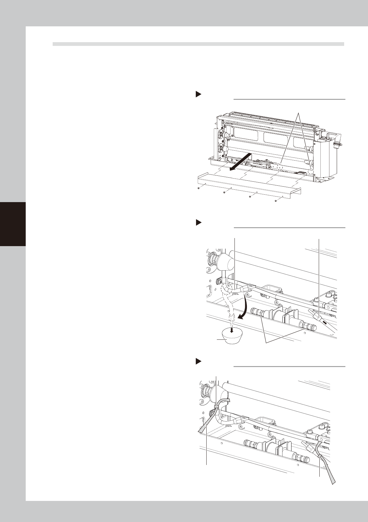
Remove the cleaner cover.
1. Remove two screws (dotted line portions
in the figure on the right) that secure the
cleaner cover.
2. Next remove the screws at 4 locations on
the near side (see drawing).
3. Raise the cover upward and then pull
toward you to remove it.
63413-N1-00
2
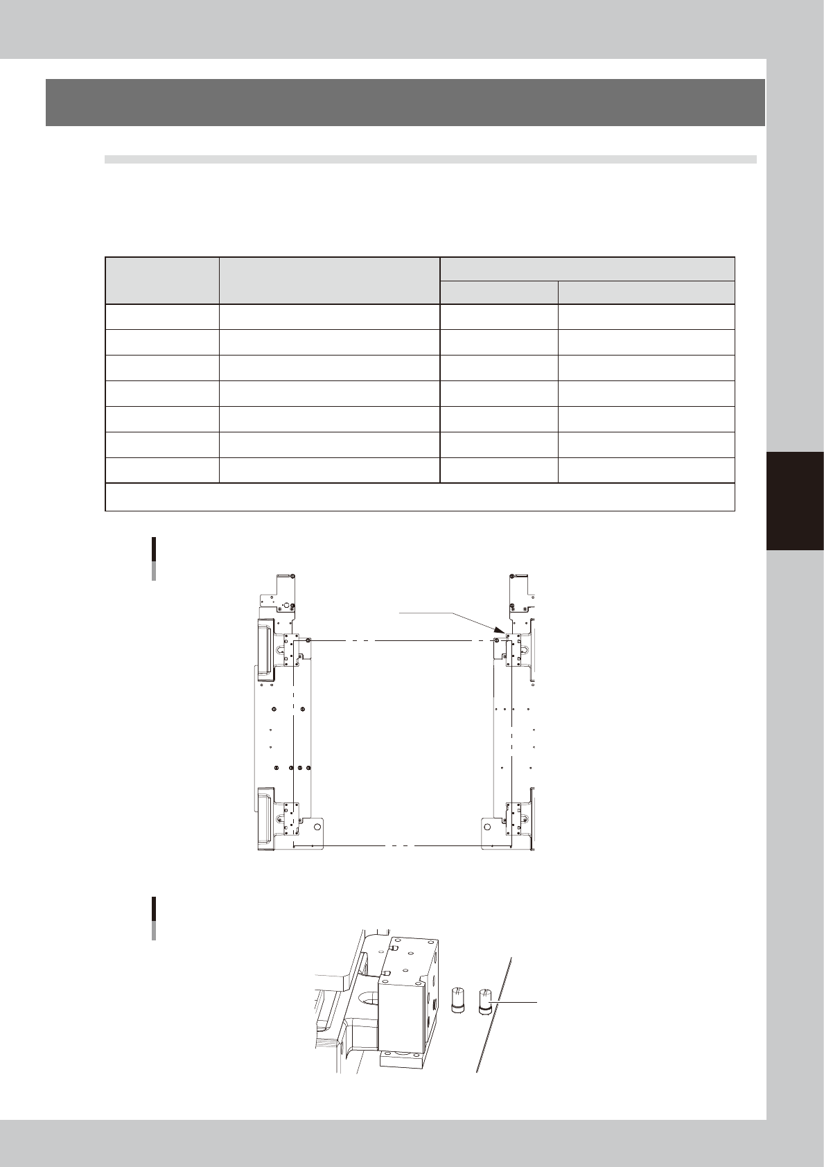
Remove the joints.
Remove the joints from two locations, one
on the head side and the other on the
bottle side from the shut-off valve joint. Use
caution because alcohol remaining in the
hose will come out when the joint on the
head side is removed.
1. Remove the head side joint in the bent
state as shown by the dashed line in the
figure on the right.
2. Prepare a container, free the bent
location and let the alcohol drain into
the container.
3. Remove the bottle side joint and then
quickly point it upward to let the alcohol
in the hose return back to the bottle.
63414-N1-00
3
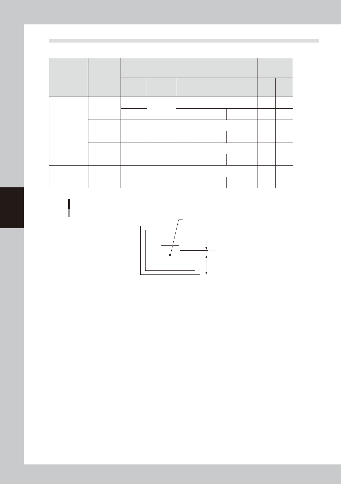
Mark the hoses you removed.
Mark the two hose sections you removed in
step 2 by winding yellow ribbon or a similar
item around them.
63415-N1-10
4
Reattach the cleaner cover.
Reinstall the cleaner cover in the reverse of
the procedure that you removed it in step 1.
Place a ribbon on the outer side of the
cover so that others will know that the joints
were removed.
n
Resetting operation
Connect the hoses in the reverse of the "Blocking the
solvent path" procedure and refill with solvent by
referring to "6.2 Refilling the cleaning solvent" in this
Chapter. When finished refilling, operate the solvent
pump to make sure it operates correctly.
Removing the cleaner cover
Step 1
First, remove the screws at 2 locations.
Removing the joints
Step 2
Joint (to head)
Shut-off valve joint
Container
Joint (to bottle)
Hose markings
Step 3
Marking (yellow ribbon, etc.)
Marking
As seen from outside the cover
4-15
4
Daily operation
7. Compatible masks
7.1 Mask size and mask stopper pin position
The mask stopper pin position must be changed according to the mask frame size to be used as shown below.
One screw-type mask stopper pin sets the left end position of the mask frame. Screw this stopper pin into one
of the "F" positions when the front conveyor rail is fixed, or one of the "R" positions when the rear conveyor rail
is fixed.
n
Mask frame size and stopper pin position
Mask frame size
L (mm) × W(mm)
Applicable board dimensions
L (mm) × W(mm)
Mask frame stopper pin position
L direction W direction
750 × 750 L50 × W50 (min.) to L510 × W460 (max) A Not used.
750 × 650 L50 × W50 (min.) to L510 × W350 (max.) A 2 (2 locations)
736 × 736 L50 × W50 (min.) to L510 × W460 (max.) B 1 (2 locations)
650 × 550 L50 × W50 (min.) to L330 × W250 (max.) C 3 (2 locations)
600 × 550 L50 × W50 (min.) to L330 × W250 (max.) D Mask adaptor (option)*
584 × 584 L50 × W50 (min.) to L330 × W250 (max.) E Mask adaptor (option)*
550 × 650 L50 × W50 (min.) to L330 × W250 (max.) F Mask adaptor (option)*
*See "7.3 Using the mask adaptor" in this chapter for the mask adaptor (option).
TIP : Store the pins that are not in use.
A
B C DF
E
11
22
3 3
Mask frame size and stopper pin position
Mask clamp
Mask frame L
Mask frame W
63422-N1-10
Mask stopper pin
Mask stopper pin
63423-N1-00
4-16
4
Daily operation
7.2 Mask frame dimensions and mask standard position
n
Mask frame dimensions and mask standard position
Specifications
Applicable
mask frame
size (mm)
Mask standard position
Standard
position
offset
Setting X direction
Y direction
A: From outside of mask frame (mm)
B: From center of mask (mm)
X Y
YCP10
L750×W750
Center
Center
0 0
Center A 145 B 230 0 0
L736×W736
Center
Center
Center 0 0
Center A 138 B 230 0 0
L650×W550
Center
Center
Center 0 0
Front A 150 B 125 0 0
Minami Kogaku L750×W650
Center
Center
Center 0 0
Front A 150 B 175 0 0
Mask standard position is “Front”.
Mask standard position “Front”
Mask center
A
B
Standard position
63424-N1-00