YCP10 Users_E.pdf - 第263页
2-16 2 Inspection and maintenance n Double squeegee (Squeegee scraper) Squeegee scraper Part No. Part name Q'ty Notes Standard MET AL W -SQG KHT -M71C3-00X MET AL SQG.,530 1 530 mm KGY -M71R3-01X MET AL SQG.,440 1 4…
2-15
2
Inspection and maintenance
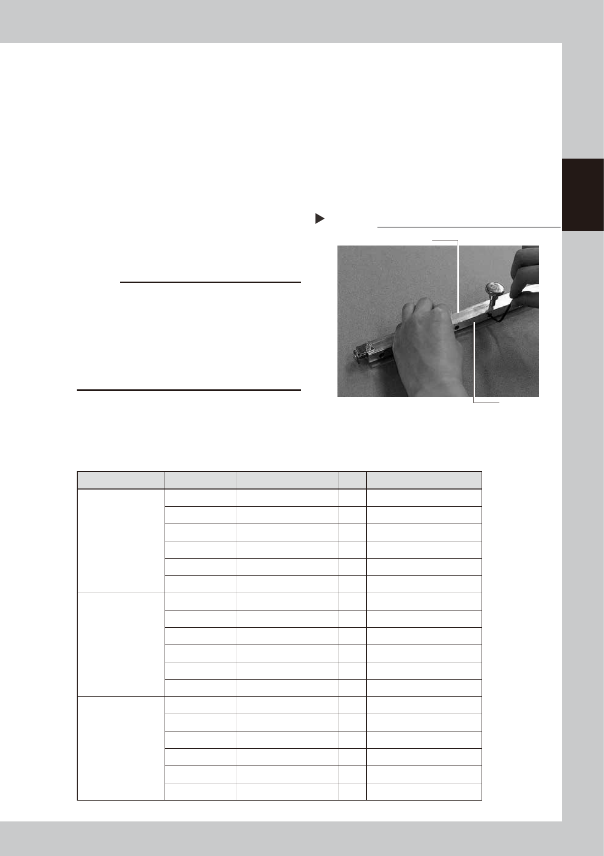
3.2.2 Urethane squeegee scraper
The edge of the urethane squeegee scraper is worn away as it is used. If the edge is worn away or chipped,
loosen the bolts that fasten the urethane scraper from the sides and replace it with a new one.
1
Remove the side plates.
Remove the side plates from both sides of
the squeegee.
2
Loosen the squeegee frame.
Use an Allen wrench to remove the bolts of
the plate that fasten the squeegee scraper.
3
Install a new squeegee scraper.
Sandwich a new squeegee scraper by the
frame and plate and tighten the bolts with
an Allen wrench.
53209-N1-00
c
CAUTION
When tightening the bolts of the urethane squeegee
scraper, gradually tighten the bolts from the center
portion to the outer portion in order with even tightening
torque. If you start tightening the bolts from the outer
portion, the center portion of the urethane part may be
bent. Additionally, it is strongly recommended to install
a new squeegee scraper with the urethane part kept
pushed against the flat surface, such as a level block.
4
Install the side plates.
Install the side plates you have removed in
the above step on the squeegee in the
reverse order of removal work.
n
3S squeegee (Squeegee scraper)
Squeegee scraper Part No. Part name Q'ty Notes
Standard METAL 3S
KHT-M71AA-A0X METAL SQG.WELD,3S 530 1 530 mm
KGY-M71EA-A0X METAL SQG.WELD,3S 44 1 440 mm
KGY-M71DA-A0X METAL SQG.WELD,3S 40 1 400 mm
KGY-M71CA-A0X METAL SQG.WELD,3S 35 1 350 mm
KGY-M71BA-A0X METAL SQG.WELD,3S 30 1 300 mm
KGY-M71AA-A0X METAL SQG.WELD,3S 25 1 250 mm
For half-etching
KHT-M71AA-B0X METAL (S)WELD,3S 530 1 530 mm
KGY-M71EA-B0X METAL SQG.(S)WELD,3S 1 440 mm
KGY-M71DA-B0X METAL SQG.(S)WELD,3S 1 400 mm
KGY-M71CA-B0X METAL SQG.(S)WELD,3S 1 350 mm
KGY-M71BA-B0X METAL SQG.(S)WELD,3S 1 300 mm
KGY-M71AA-B0X METAL SQG.(S)WELD,3S 1 250 mm
URETHANE 3S
KHT-M71BB-00X URETHANE ASSY,3S 530 1 530 mm
KGY-M71K3-A0X URE.SQG.ASSY,3S 440 1 440 mm
KGY-M71J3-A0X URE.SQG.ASSY,3S 400 1 400 mm
KGY-M71H3-A0X URE.SQG.ASSY,3S 350 1 350 mm
KGY-M71G3-A0X URE.SQG.ASSY,3S 300 1 300 mm
KGY-M71F3-A0X URE.SQG.ASSY,3S 250 1 250 mm
Urethane squeegee scraper
Step 3
Squeegee frame
Plate
2-16
2
Inspection and maintenance
n
Double squeegee (Squeegee scraper)
Squeegee scraper Part No. Part name Q'ty Notes
Standard METAL W-SQG
KHT-M71C3-00X METAL SQG.,530 1 530 mm
KGY-M71R3-01X METAL SQG.,440 1 440 mm
KGJ-M7183-03X METAL SQG.,400 1 400 mm
KGJ-M7173-03X METAL SQG.,350 1 350 mm
KGJ-M71A3-01X METAL SQG.,300 1 300 mm
KGJ-M7193-01X METAL SQG.,250 1 250 mm
For half-etching METAL
W-SQG
KHT-M71C3-10X METAL SQG.(S),530 1 530 mm
KGY-M71R3-10X METAL SQG.(S),440 1 440 mm
KGJ-M7183-10X METAL SQG.(S),400 1 400 mm
KGJ-M7173-10X METAL SQG.(S),350 1 350 mm
KGJ-M71A3-10X METAL SQG.(S),300 1 300 mm
KGJ-M7193-10X METAL SQG.(S),250 1 250 mm
URETHANE W-SQG
KHT-M71E3-00X URETHANE SQG.,530 1 530 mm
KGY-M71W3-00X URETHANE SQG.,440 1 440 mm
KGJ-M710C-E0X SQUEEGEE,400 1 400 mm
KW3-M7126-00X SQUEEGEE,M 1 350 mm
KGJ-M71C3-00X URETHANE SQG.,300 1 300 mm
KGJ-M71B3-00X URETHANE SQG.,250 1 250 mm
c
CAUTION
Parts (Part No.) listed above is current as of the issue date of this manual. When ordering a replacement part, please
check for the latest information.
c
CAUTION
Part Nos. are subject to change without prior notice. When ordering a replacement part, contact your local sales
dealer to check its part No.
2-17
2
Inspection and maintenance
3.3 Suction-blower unit
The suction-blower unit is always operated even when the machine is in emergency stop. It is therefore
necessary to clean and replace the filter and replace the blower hose periodically.
3.3.1 Replacing the filter
To clean and replace the filter, follow the steps below.
n
Required tools
• Phillips screwdriver
• Replacement filter (KGY-M3710-4XX INL FILTER ELEMENT)
• Air blow tool (option)
1
Move the printing table and
cleaning unit.
Open the [Setup] tab on the Setup screen
and press the [Manual Cleaning] button.
The printing table is then connected to the
cleaning unit and they move backward.
e
2
After pressing the emergency stop
button, open the upper door and
front panel.
To ensure the work safety, be sure to put the
machine in the emergency stop state.
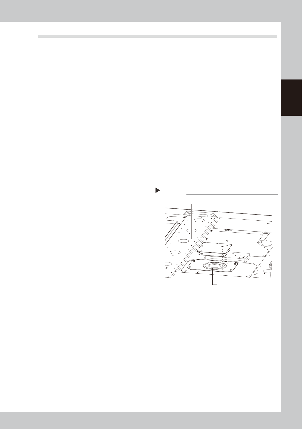
3
Remove the filter cover.
Use a Phillips screwdriver to remove 4
mounting screws and detach the cover.
53210-N1-00
4
Take out the filter and clean it.
Take out the ring-shape filter and blow it
from the outside and inside using an air blow
tool.
If the filter is contaminated significantly,
replace it with a new one.
5
Return the filter to its original
position.
Insert the filter to its original position and
close the cover.
6
Release the connection between
the printing table and cleaning
unit.
Open the [Unit]-[Cleaner] tab and press the
[Cleaner Connect] button to release the
connection.
The cleaning unit will return to its original
position, and it is then secured.
Removing the filter cover
Step 3
Mounting screws (4 places)
Filter
Filter cover