YCP10 Users_E.pdf - 第57页
1-16 1 Part names and functions 5.2 Suction unit T he YCP10 has a suction blower unit built into the inside of the front panel of the mac hine main unit. T his suction unit sucks up solder adhering to the mask apertures …
1-15
1
Part names and functions
5. Cleaning unit
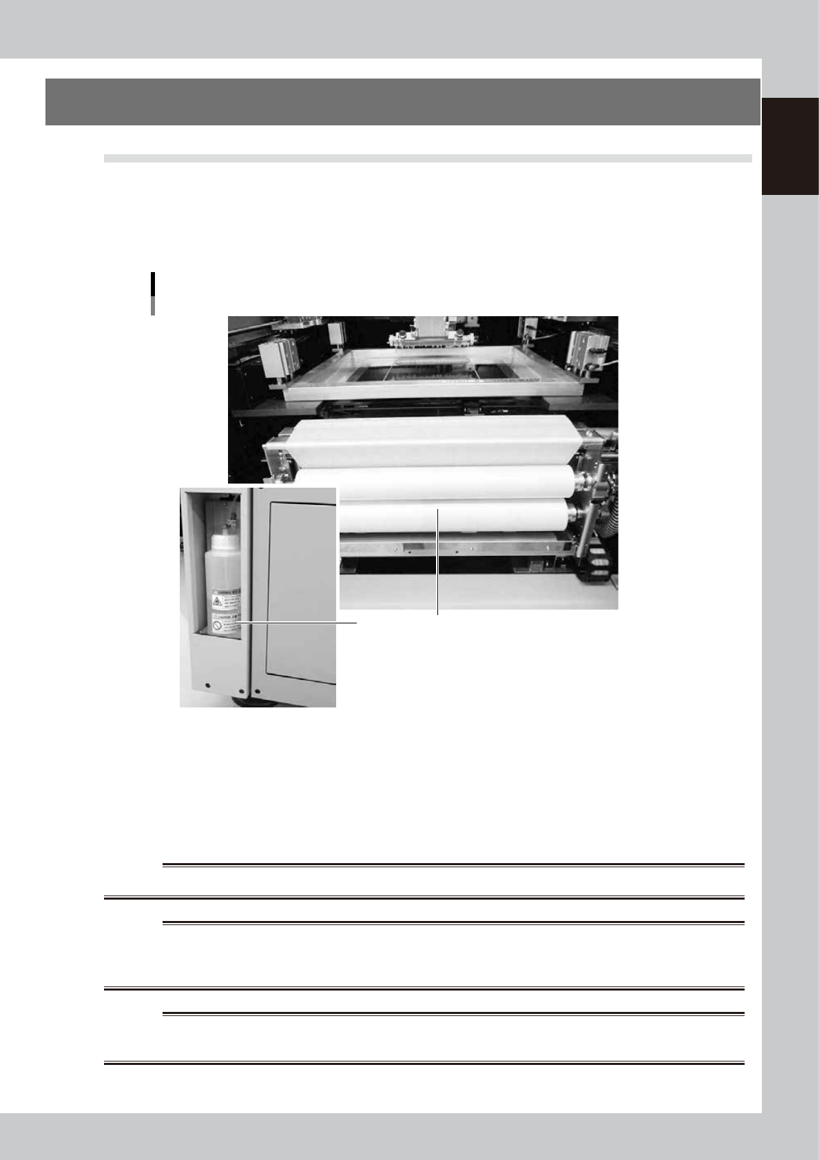
5.1 Cleaning unit
When you open the machine front panel, you will see the cleaning unit installed under the printing table. The
cleaning unit uses a gauze roll to wipe away solder adhering to the mask apertures and solder coming out of
the backside of the mask while vacuuming. Cleaning can be performed in AUTO mode or MANUAL mode. In
AUTO mode, you can further select wet mode using a solvent (alcohol) or dry mode using the cleaning gauze
only.
Cleaning unit and solvent bottle
12
63114-N1-00
1. Gauze roll
Wipes away solder and flux coming out of the backside of the mask. To replace the used gauze roll see "5. Replacing the
cleaning gauze roll" in Chapter 4.
2. Solvent bottle (lower left portion of main unit)
Lets solvent soak into the cleaning gauze to liquefy remaining solder during mask cleaning.
Insert the connector on the bottle cap into the mating connector on this machine.
w
WARNING
TO REFILL THE SOLVENT BOTTLE, ALWAYS USE ISOPROPYL OR ETHYL ALCOHOL. OTHER SOLVENTS MAY CAUSE FIRES.
w
WARNING
NEVER USE ACETONE FOR CLEANING. ACETONE MAY DAMAGE SOLVENT TUBES OR THE CLEANING UNIT, CAUSING
CLEANING FLUID TO LEAK THROUGH DAMAGED PARTS. ALSO BE SURE TO USE FRESH CLEANING FLUID. DO NOT USE OLD
(USED) CLEANING FLUID.
w
WARNING
BE CAREFUL WHEN USING ISOPROPYL ALCOHOL, SINCE INHALING ALCOHOL FUMES OVER EXTENDED PERIODS CAN BE
HAZARDOUS TO HEALTH.
1-16
1
Part names and functions
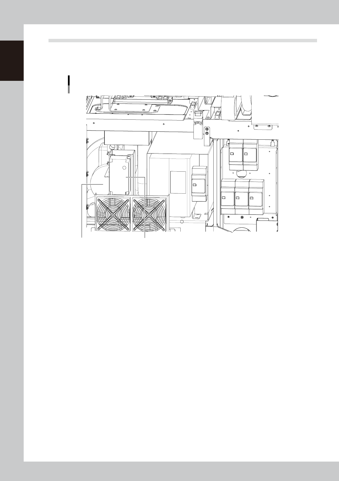
5.2 Suction unit
The YCP10 has a suction blower unit built into the inside of the front panel of the machine main unit. This
suction unit sucks up solder adhering to the mask apertures and solder coming out of the backside of the mask
during automatic cleaning.
Suction unit
Suction filter unit Inverter
63115-N1-00
1-17
1
Part names and functions
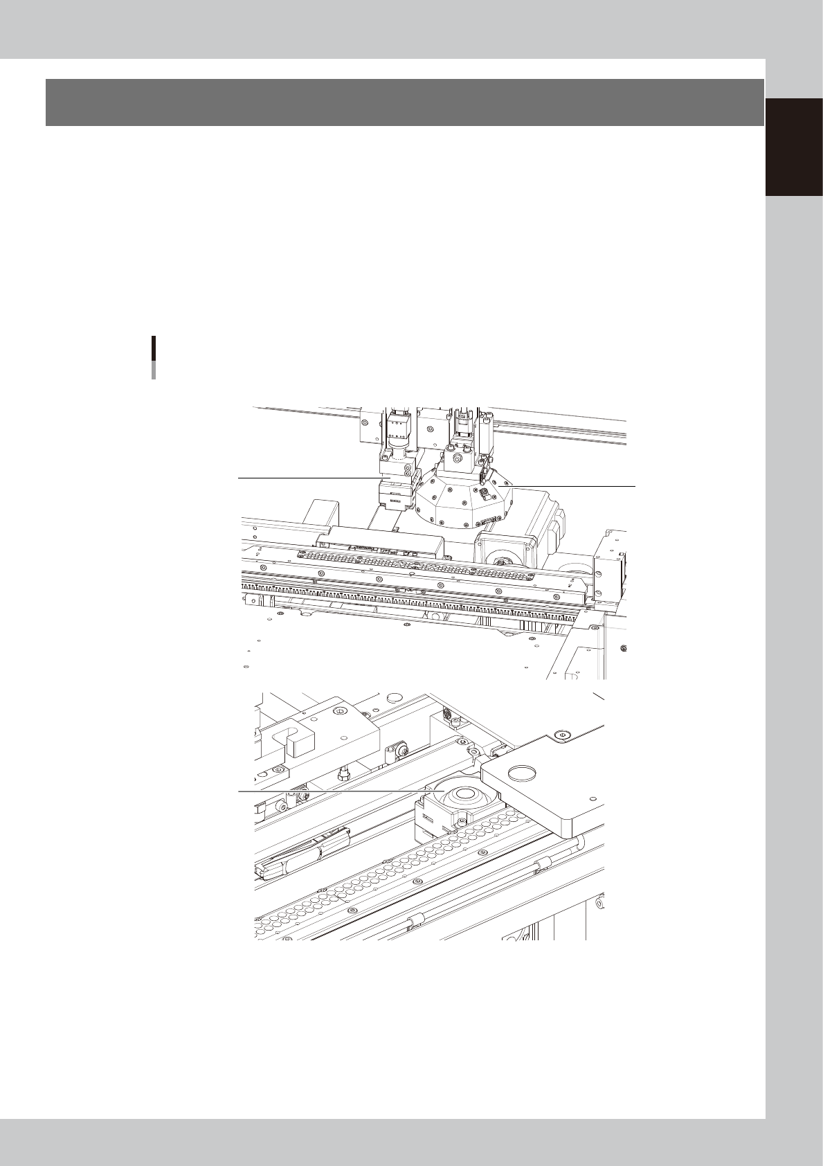
6. Vision camera unit
This machine is equipped with a "board vision camera" for recognizing fiducial marks and land patterns on
boards; and a "mask vision camera" for recognizing fiducial marks on the backside of masks (stencils) and
mask apertures. These cameras are also used as a teaching unit to perform teaching.
A "solder-print inspection camera" and a light are added to machines which have the optional solder-print
inspection function.
These cameras are used as a teaching unit to perform the teaching.
• The "board vision camera", "solder-print inspection camera (option)" and "lighting unit (option)" are installed on the
camera X-axis (CX-axis) and move only in the X direction. These cameras synchronize with the Y-axis to recognize
fiducial marks on the board surface.
• The "mask vision camera" is installed in front of the fixed conveyor rail and moves only in the X-direction. This camera
interlocks with the Y-axis to recognize the fiducial marks on the mask backside and mask apertures.
Vision camera unit
3
2
1
■ Board vision camera and solder-print inspection camera (Option)
■ Mask vision camera
63116-N1-00
1. Board vision camera, Lighting unit
This vision camera and lighting unit recognize the surface of a board clamped on the conveyor.
2. Mask vision camera, Lighting unit
This vision camera and lighting unit recognize the backside of a mask (stencil) clamped on the printing table.
3. Solder-print inspection camera (option), Lighting unit (option)
High-resolution, wide field-of-view camera and lighting unit installed in the YCP10 with an optional solder-print
inspection function. Refer to the separate "Option manual" for detailed information.