YCP10 Users_E.pdf - 第46页
1-5 1 Part names and functions 2.1 Operation panel buttons T he operation panel buttons are provided on the front and rear of the machine to run major commands frequently used to operate the mac hine. Each button is lit …
1-4
1
Part names and functions
2. Operation panels and data input units
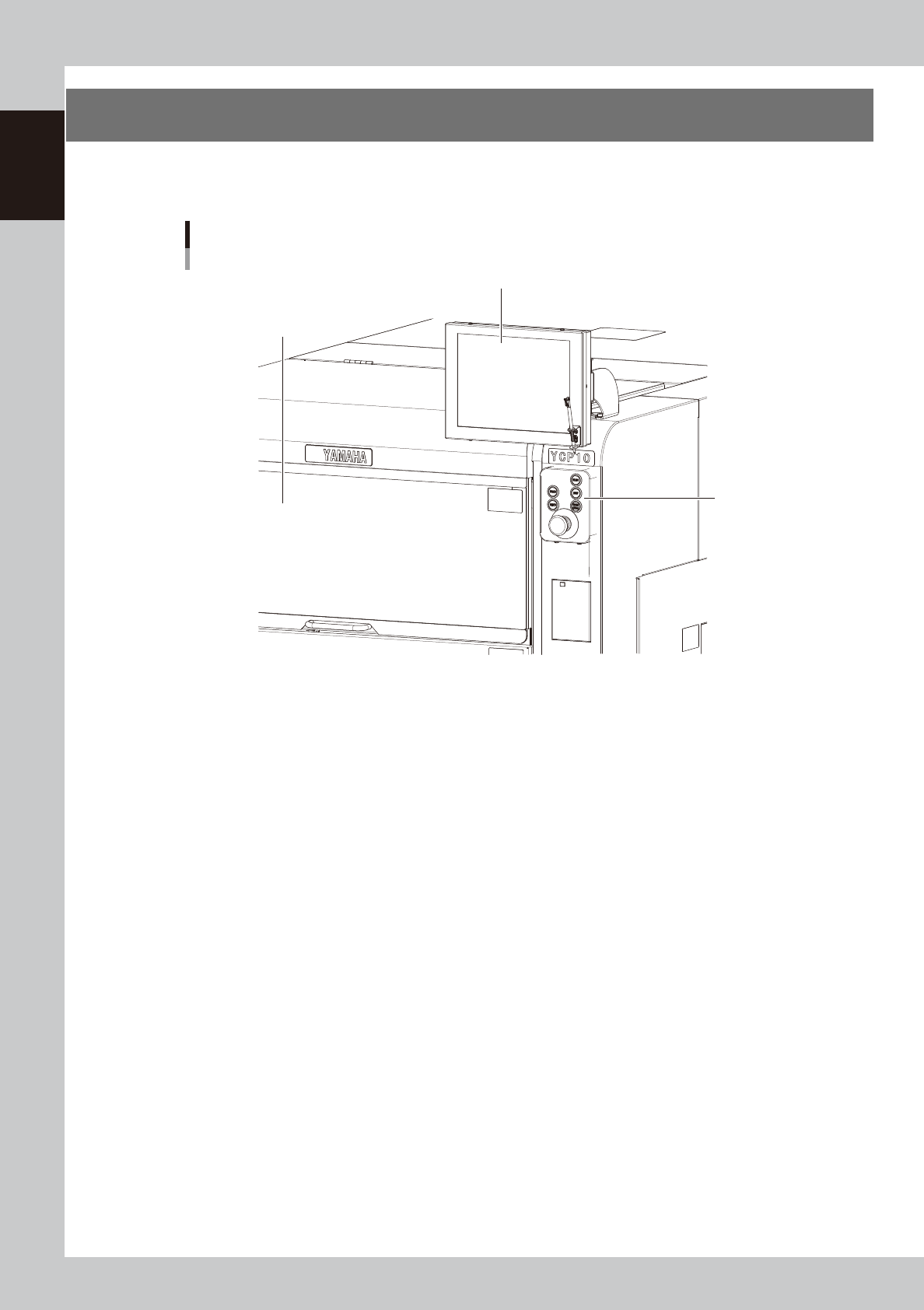
Operation panel buttons and operation display used to operate this machine or input the data are installed.
This section describes the functions of these units.
Operation panel and data input unit
Operation panel
buttons
Operation display
Upper door (safety cover)
63103-N1-00
1-5
1
Part names and functions
2.1 Operation panel buttons
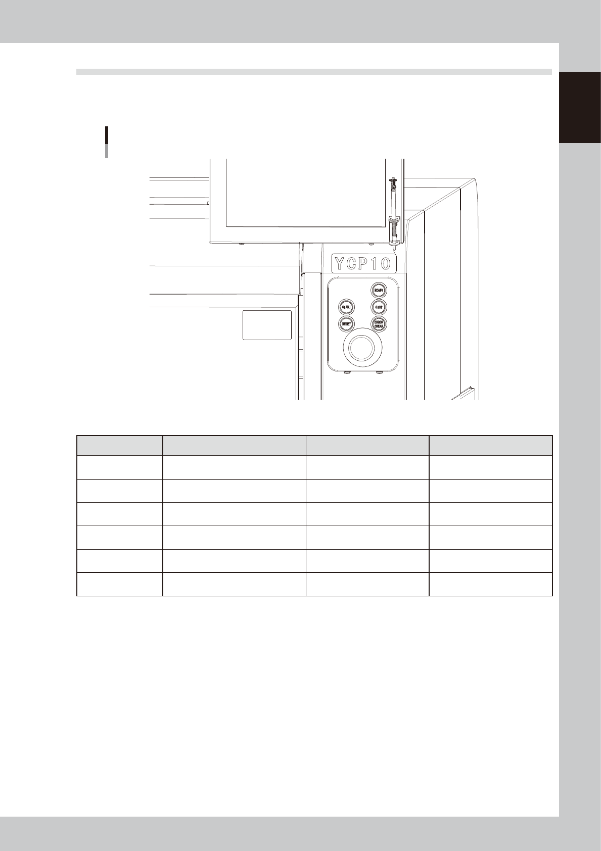
The operation panel buttons are provided on the front and rear of the machine to run major commands
frequently used to operate the machine. Each button is lit while turned on. The colors used for the operation
panel are the same as those specified for the signal light (signal tower).
Operation panel buttons
63104-N1-00
n
Operation panel button functions
Button name Use the button to: OFF ON
READY
Release emergency stop and turn the
servo on.
• SERVO OFF
(Motor power OFF)
• SERVO ON
(Motor power ON)
RESET
Stop automatic operation and return to
standby for board production.
• Machine is in normal operation
or stopped.
• Machine has been reset.
START (green)
Perform operation according to board
data.
• Machine is stopped. • Machine is in normal operation.
STOP (Red / White)
Interrupt automatic operation. (Press
START to resume operation.)
• Machine is in normal operation. • Error occurred.
ERROR CLEAR
(Yellow / Blue)
Stop buzzer sound and clear error
screen.
• Machine is in normal operation. • Error occurred.
EMERGENCY STOP
Trigger emergency stop. Turn to the
right to release it.
1-6
1
Part names and functions
2.2 Operation display screen
Machine operation and data editing procedures are performed at the operation display screen (touch-panel
specifications). A touch pen is used to select the onscreen buttons and parameter items. Be sure to return the
touch pen to its holder when it is not in use.
Touch screen (option)
Operation display screen
(Touch-panel)
Holder
Touch pen
63105-N1-00
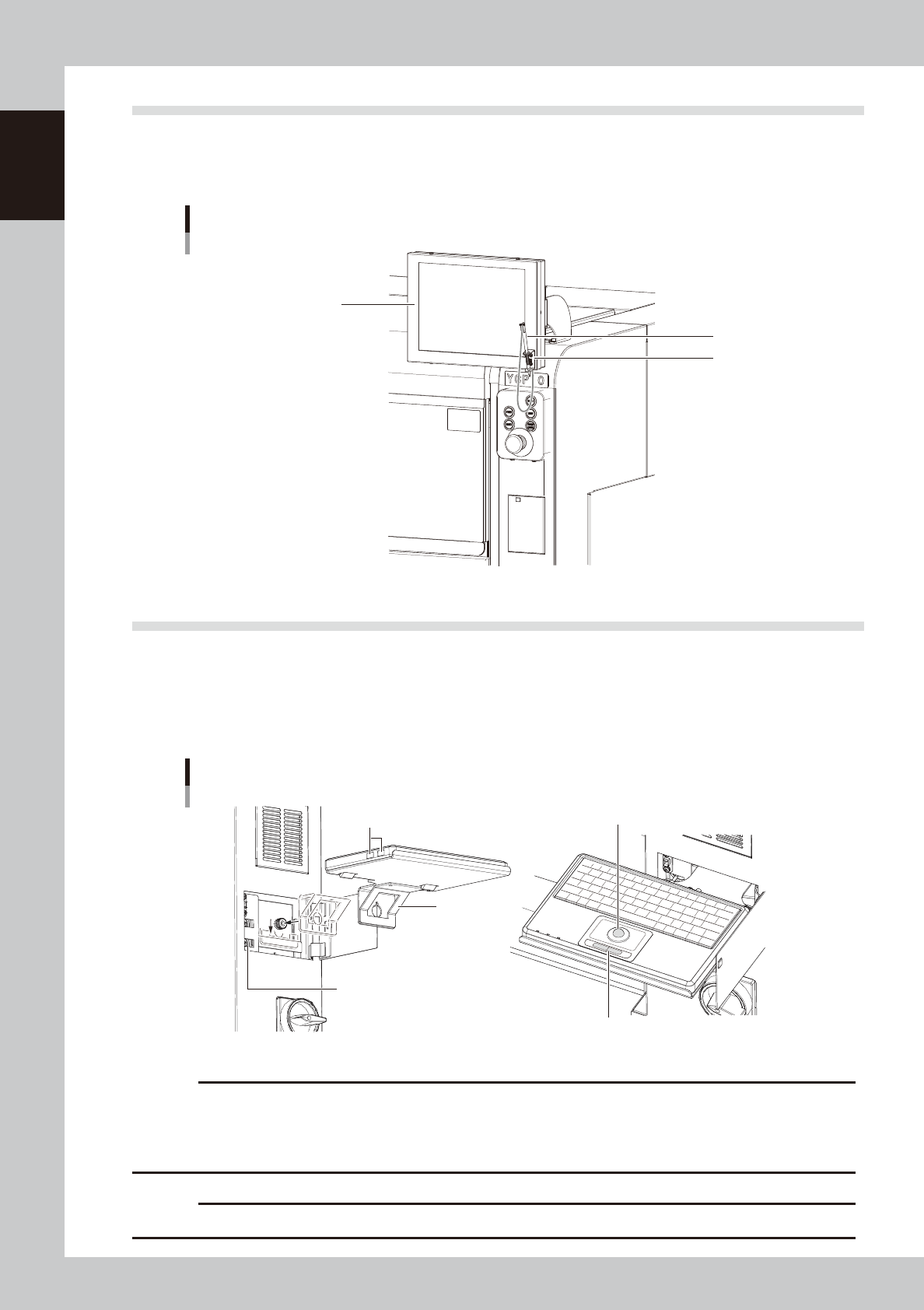
2.3 Keyboard (option)
An optional keyboard for operation and data editing, etc., can be added to the machine's configuration if
desired. The keyboard's track-ball is used to move the cursor to the desired onscreen buttons and parameter
items which are then selected by pressing the left-click button (right-clicking is not available).
When using the keyboard, install the bracket on this machine and connect the USB terminal of the keyboard to
the USB port on this machine.
Keyboard
Bracket
These USB ports are not allowed to use.
USB port for keyboard connection
Track-ball
Left/right button
63106-N1-00
c
CAUTION
The USB port shown in the illustration is for the keyboard only. (Only keyboards which do not require a -101 dedicated
driver are supported.) Do not connect other USB devices to this port.
Moreover, connecting 2 or more keyboards will disable exclusive access control, and therefore stop keyboard
operation.
c
CAUTION
Do not use the USB ports of the keyboard. The USB port may not operate correctly due to insufficient power.