YCP10 Users_E.pdf - 第287页
A-7 Appendix 2. Inver ter (suction unit) The suction unit built into the YCP10 uses an inverter to ensure stable operation. If a problem occurs with the inverter or suction unit, an error message appears on the YSP opera…
A-6
Appendix
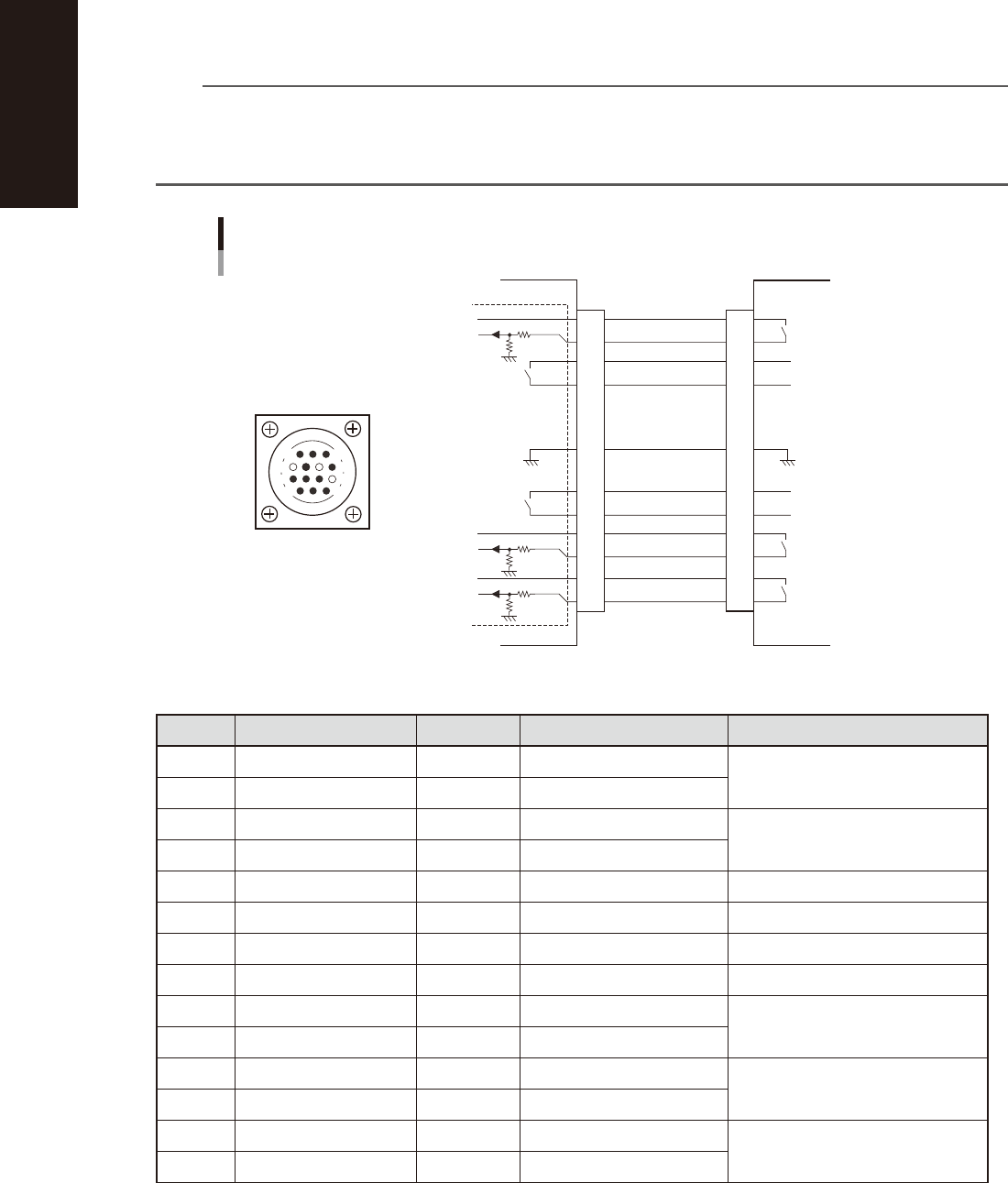
1.3.2 NEXT INTERFACE connector
When the following three conditions are met, the NEXT INTERFACE circuit in the machine allows the board to
be carried out.
1. Machine is ready for carrying out a board (BA OUT: ON)
2. Board carry-in signal is input from the downstream machine. (BUSY IN [N0100320]: ON)
3. Automatic operation signal is input from the downstream machine. (LR IN [N0100323]: ON)
n
NOTE
• When the automatic operation signal (LR IN) from the downstream machine turns off during transfer of a board,
the machine stops temporarily carrying out the PC.
• When the board being carried out is detected by the exit sensor, the BA OUT signal turns off.
• Carrying out the board is finished when both the BUSY IN and BA OUT turn off.
1
2
3
4
5
6
7
8
9
10
11
12
13
14
BUSY IN
(N0100320)
+24V
+24V
UR OUT(T01000E6)
LR IN
(N0100323)
+24V
LS IN
(N0100324)
BA OUT
(T01000E5)
Signal output during
board carry-in
Signal input to request
board carry-out
Signal input during
automatic operation
Signal output during
automatic operation
Signal output during
waiting for board
between machines
I/O BOARD
GND GND
14
11
12
7
4
8
3
1
NEXT INTERFACE circuit
NEXT INTERFACE
connector
NEXT INTERFACE on this machine
Downstream machine
AMP 206043-1
(14-pin receptacle)
53A07-N1-00
n
Board transfer signal specifications (NEXT INTERFACE)
Pin No. Signal name Address I/O specifications Signal specifications
1 +24V Input common (+24V)
Signal input during board carry-in
2 BUSY IN N0100320 Voltage input
3 BA OUT T01000E5 Relay contact output
Signal output to request board carry-out
4 BA OUT T01000E5 Relay contact output
5 With dummy pin Prevents misinsertion
6 NC
7 GND
8 NC
9 UR OUT T01000E6 Relay contact output
Signal output during automatic
operation
10 UR OUT T01000E6 Relay contact output
11 +24V Input common (+24V)
Signal input during automatic
operation
12 LR IN N0100323 Voltage input
13 +24V Input common (+24V)
Signal input during waiting for board
between machines
14 LS IN N0100324 Voltage input

A-7
Appendix
2. Inverter (suction unit)
The suction unit built into the YCP10 uses an inverter to ensure stable operation.
If a problem occurs with the inverter or suction unit, an error message appears on the YSP operation display.
In this case, check the error number shown on the inverter display panel and contact our sales office or sales
representative.
Inverter
Inside the panel at the lower portion of the front
Inverter display panel
Reset button
53A08-N1-00
n
Inverter error display
Name Description Error display
Overcurrent
protection
When the motor is restrained or suddenly reduced in speed, a large
current is charged to the inverter, causing a fault. When the inverter
detects 205% peak current of the inverter, an overcurrent occurs.
Constant
speed
Deceleration
Acceleration
Others
Overload
protection
When the inverter output current causes the motor to overload, the electronic thermal
trip in the inverter cuts off the inverter output.
Overvoltage
protection
If regenerative energy from the motor or the main power supply voltage is high,
the protective circuit activates to cut off the inverter output when the voltage of the
converter section exceeds the specification.
EEPROM
EEROR
The inverter output is cut off when EEPROM in the inverter has an error due to external
noise, excessive temperature rise, or other factor.
Undervoltage
protection
When the input voltage received by the inverter decreases, the control circuit does not
function normally. When the input voltage is below the specification, the inverter output
is cut off.
CPU error The inverter output is cut off when the inverter CPU has a malfunction or an error.
External trip
When the external equipment or unit has an error, the inverter receives the
corresponding signal and cuts off the output.
USP error
The USP error is indicated when the power is turned on with the inverter in the RUN
state. (Enabled when the USP function is selected.)
Ground fault
protection
GROUND fault is detected between the inverter output section and the motor when the
power is turned on, to protect the inverter.
Input
overvoltage
protection
When the input voltage is higher than the specified value, it is detected 100 seconds
after power is turned on and the output is cut off.
Temperature
error
When the temperature in the main circuit increases due to cooling fan stop, the inverter
output is cut off. (Only for the model type with cooling fan)
Waiting on
account of
undervoltage
Waiting with the output turned off, because the inverter receiving voltage has dropped.
c
CAUTION
If a trouble or problem is found, contact your distributor.
Version 2.10
User’s Manual February 2019