YCP10 Users_E.pdf - 第152页
5-21 5 Cr eating and setting the data 5. Squeegee data setting The following parameter items can be checked and edited on the [Print]-[Squeegee] tab. [Print]-[Squeegee] tab 1 64522-N1-10 1: Squeegee T ype Select "3S…
5-20
5
Creating and setting the data
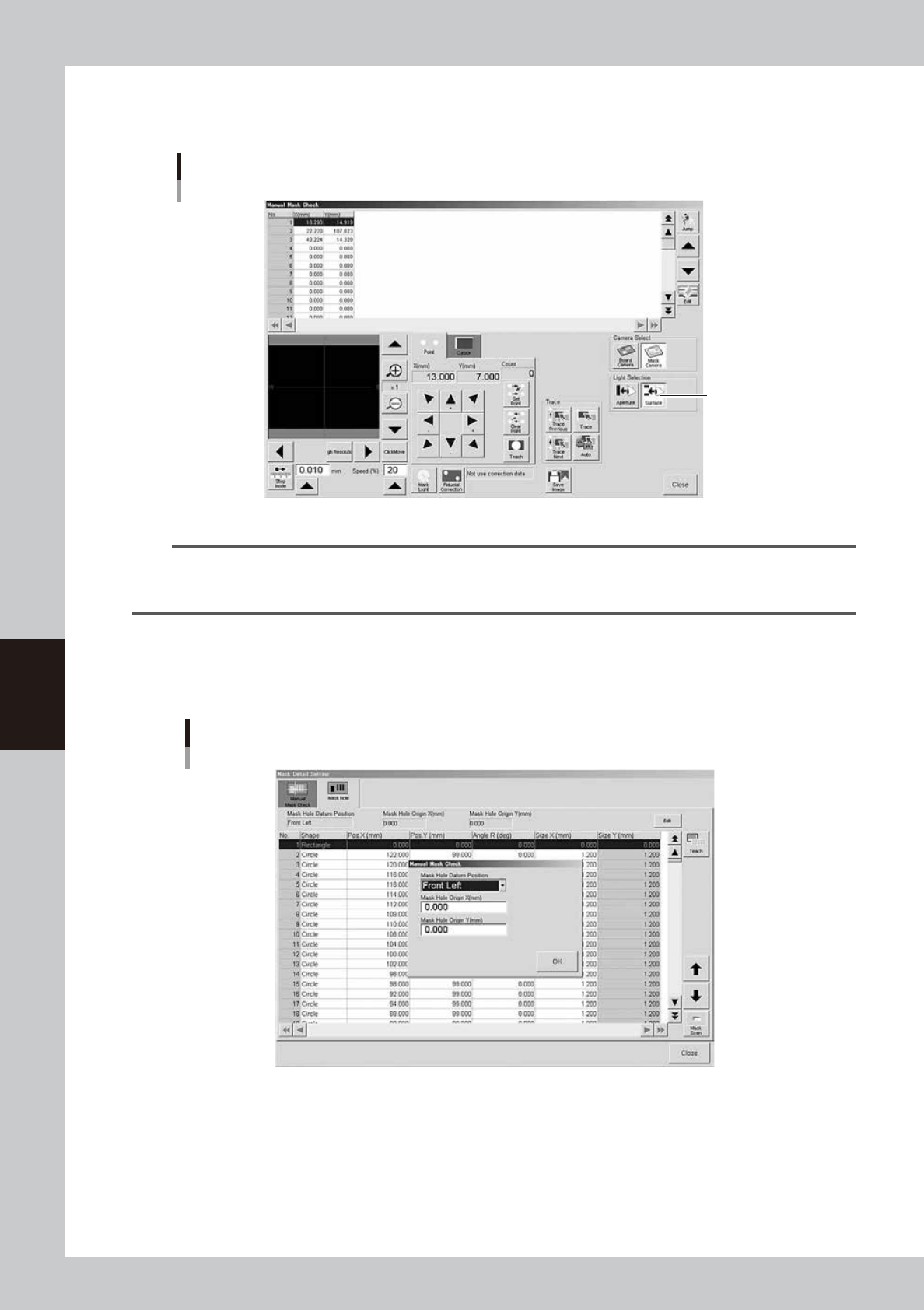
To set the lighting for inspecting excess solder and flux spreading to the backside of the mask, press the [Light] button
while the [Surface] button is depressed. You can then change to an optimum lighting level on the lighting setup window.
In either case, closing the window automatically stores the changes you made into the board data.
"Teach/Trace" window for visual mask check
[Surface] button
[Surface] button
64521-N1-00
n
NOTE
By storing the visual check lighting levels for the mask aperture and backside, you can switch to each lighting level by
just pressing the [Aperture] button for the mask aperture visual check or the [Surface] button for the mask backside
visual check.
l
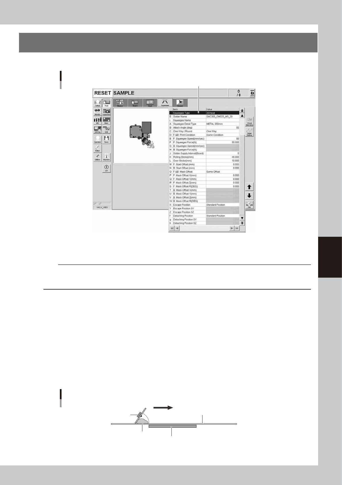
Mask aperture coordinate setting
When you press the [Detail] button on the [Print]-[Mask] tab, the following screen appears for setting the mask aperture
coordinates.
[Mask hole] tab
64547-N1-00
This function is available only for machines equipped with an optional print inspection camera.
For details, see "2.3 Using the mask scan function" in the separate Option Manual.
5-21
5
Creating and setting the data
5. Squeegee data setting
The following parameter items can be checked and edited on the [Print]-[Squeegee] tab.
[Print]-[Squeegee] tab
1
64522-N1-10
1: Squeegee Type
Select "3S Head" when using the 3S squeegee head. Select "Double squeegee" when using the optional double squeegee.
TIP
The squeegee type has been set in the machine data prior to shipment according to the machine specifications. So
the same squeegee type as set in the machine data must be selected here. If not the same squeegee type, an error
is issued.
E: Solder Name
Enter the name or comment on the solder to be used. You can leave this field blank.
i: Squeegees Name
Enter the name or comment on the squeegees to be used. You can leave this field blank.
A: Squeegee Detail Type
When the squeegee type has been set to "3S Head" or "Double squeegee," specify the kind and size.
B: Attack Angle (deg.)
This parameter is available only when the squeegee type is set to "3S Head." (This parameter is not displayed when the
squeegee type is set to "Double Squeegee.")
Set the angle between the 3S squeegee and the mask surface appropriate to solder printing. The setting range is from 45
to 65 degrees. (Default setting is 55 degrees.)
Attack angle (3S head only)
Solder
Attack angle (scraper angle)
Board
Mask
3S squeegee scraper
Printing direction
63514-N1-00
5-22
5
Creating and setting the data
C: One Way/Round
Select whether to print solder in one direction or in both directions.
D: F. & B. Print Condition
Select whether to use the same conditions for the forward and backward printing. When this parameter is set to "Same
Condition", the forward and backward printing operations are performed under the conditions specified for the "F.
Squeegee Speed" and "F. Squeegee Force", and the settings for the "B. Squeegee Speed" and "B. Squeegee Force" are
disabled.
E, G: F. Squeegee Speed (mm/sec), B. Squeegee Speed (mm/sec)
Set the forward and backward squeegee movement speeds to print solder. Find an optimum speed while checking the
scraped state of the solder on the mask. If this speed is too fast, the squeegee may not scrape solder properly. If too slow,
solder may spread into the backside of the mask.
F, H: F. Squeegee Force (N), B. Squeegee Force (N)
Set the force (pressure) to apply a load to the squeegee during printing in the forward and backward directions. Check
the scraped state of the solder on the mask to find an optimum squeegee pressure. Set this pressure at a lower pressure as
long as the solder is scraped properly. A larger squeegee pressure is required as the squeegee speed is set faster.
J: Solder Supply Interval (Board)
Set the number of boards to be printed per one supply of solder, based on the amounts of solder supplied and used
during printing.
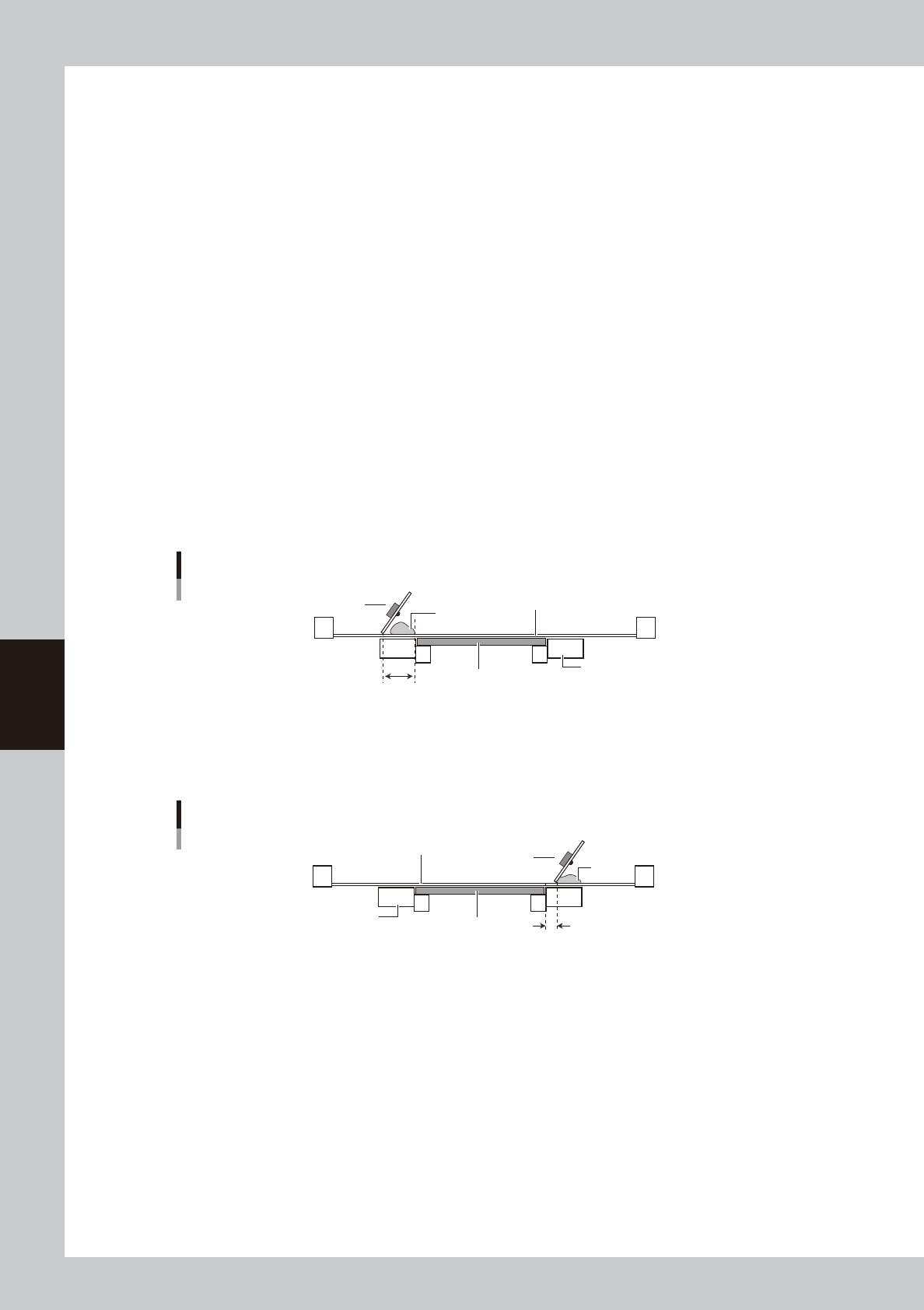
K: Rolling Stroke (mm)
Specify the distance (millimeters) from the position at which the squeegee lands on the mask to the edge of the board.
Usually set to 40 to 45 mm.
Rolling stroke
Squeegee
Solder
Mask surface
Conveyor
Board
Rolling stroke
63515-N1-00
L: Over Stroke (mm)
Specify the distance (millimeters) from the other edge of the board to the position at which the squeegee takes off the
mask after printing solder. Usually set to 5 to 10 mm.
Over stroke
Solder
Board
Conveyor
Mask surface
Over stroke
Squeegee
63516-N1-00