YCP10 Users_E.pdf - 第269页
2-22 2 Inspection and maintenance 5 Clean the guide and pulley s. 1. Use a vacuum assembly (option) to suction the belt wear debris on the belt guide and sensors, etc. 2. Use a plastic spatula or similar tool to remove t…
2-21
2
Inspection and maintenance
3.5 Replacing the conveyor transfer belt
If significant looseness, contamination, or scuffing is found in the conveyor transfer belt in a periodic
inspection, the conveyor belt (hereafter "belt") needs to be replaced. Follow the steps below to replace belt.
n
Required tools
• Hex wrench (2.5 mm, 3 mm, 4 mm, 5 mm)
• Permanent marker
• Brush
• Plastic spatula
• Replacement conveyor transfer belt (KLV-M9127-00X BELT CONVEYOR) (for Type A)
• Replacement conveyor transfer belt (KLV-M9127-01X BELT CONVEYOR) (for Type B)
1
Prepare for detaching belt.
See Step 1 to 3 in "2.3.1 Belt Type A" to
detach mask guide plate.
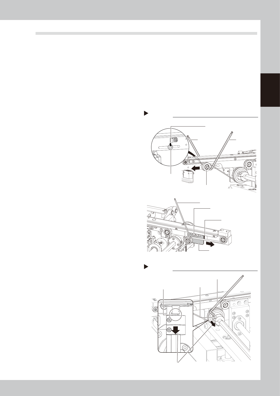
2
Mark the tension mounting position
before adjusting.
<Type A>
Mark the tensioner mounting bolt position
with permanent marker.
<Type B>
Mark the tension adjustment plate position
with permanent marker.
53214-N1-20
3
Loosen the belt tension.
<Type A>
Loosen pulley with 2 hex wrenches. Move
the pulley to the end of slot (black arrow's
direction shown at right).
<Type B>
Loosen tension adjustment plate mounting
bolts with hex wrench and move tension
adjustment plate in black arrow's direction
shown at right.
4
Detach the belt.
1. Loosen the coupling mounting bolt with
hex wrench (2.5 mm) to slide the
coupling to the machine rear side.
2. Detach the belt from pulley and pull it
from the gap between pulley and shaft.
Marking / Loosening belt
Step 2, 3
Tensioner (pulley)
Tensioner (pulley)
mounting bolt
Hex wrench
(4 mm)
Marking
Marking
<Type A>
<Type B>
Hex wrench
(5 mm)
Tension adjustment plate
mounting bolt
Tension adjustment plate
Hex wrench (3 mm)
Detaching the belt
Step 4
Coupling
Hex wrench (2.5 mm)
Slide to machine rear side.
Gap to pull out belt
2-22
2
Inspection and maintenance
5
Clean the guide and pulleys.
1. Use a vacuum assembly (option) to
suction the belt wear debris on the belt
guide and sensors, etc.
2. Use a plastic spatula or similar tool to
remove the belt wear debris adhering to
the pulley surface.
3. Use a brush or similar tool to remove the
belt wear debris caught in the belt
guides.
53218-N1-00
6
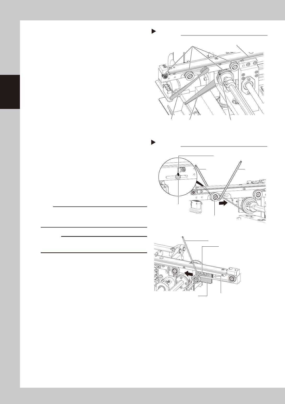
Attach a new belt.
1. Temporarily fit a new belt onto the pulley.
2. Return the coupling to its original position
and tighten the bolt.
<Type A>
3. Move the tensioner (pulley) to marked
position and then tighten bolts.
4. If belt is loose, adjust position of tensioner
(pulley) and apply tension again.
<Type B>
3. Move the tension adjustment bolt to
marked position and then tighten bolts.
4. If belt is loose, adjust position of tension
adjustment bolt and apply tension again.
53219-N1-00
n
NOTE
Make sure to use a tension meter for adjustment. See
"2.3 Adjusting the conveyor belt tension" in this chapter
for how to measure the belt tension.
c
CAUTION
Make sure not to tighten tensioner mounting bolt and
tension adjustment mounting bolt excessively.
7
Check the belt rotating condition.
1. Cancel emergency stop.
2. On the [Unit]-[Conveyor] tab, press the
[Convey In] and [Convey Out] buttons to
turn on the conveyor motor and check
the belt rotation.
3. If the slip of the motor pulley, the belt
rotation fluctuation and the deflection
are excessive, adjust the tensioner
(pulley) position and transfer a board
again and check the condition.
8
Return the mask guide plate to its
original position.
Attach the mask guide plate to conveyor by
tightening 4 bolts with hex wrench (3 mm).
Cleaning guide and pulleys
Step 5
Plastic spatula
Pulley surfaces
Brush
Belt guide
Belt wear debris
Applying belt tension
Step 6
Tensioner
Tensioner
mounting bolt
Hex wrench
(4 mm)
Marking
Marking
<Type A>
<Type B>
Hex wrench
(5 mm)
Tension adjustment plate
mounting bolt
Tension adjustment plate
Hex wrench (3 mm)
Tightening torque: 5.5 N•m
Tightening torque: 5.5 N•m

Chapter 3 Lubrication points
Contents
1. Lubrication grease and tool 3-1
1.1 Applicable grease 3-1
1.2 Grease gun 3-1
2. List of lubrication points 3-2
2.1 X-, Y-, and Z-axis 3-2
2.1.1 X1-axis and X2-axis 3-2
2.1.2 Y-axis 3-3
2.1.3 Z-axis 3-4
2.2 Printing head 3-5
2.2.1 SY-axis 3-5
2.2.2 SZ-axis 3-5
2.3 Conveyor unit 3-6
2.3.1 PU-axis 3-6
2.3.2 MX-axis 3-6
2.3.3 W-axis (Conveyor auto width adjustment) 3-7
2.4 Vision camera unit 3-8
2.4.1 CX-axis 3-8
2.5 Suction-blower unit 3-9
2.5.1 Blower hose guide 3-9
2.6 Cleaning unit 3-9