YCP10 Users_E.pdf - 第77页
3-1 3 Printing guide 1. Flow of printing condition setting The following diagram shows the flow of the condition setting (data setting) and the setup work necessar y to perfor m the printing with excellent quality . • Be…

3-1
3
Printing guide
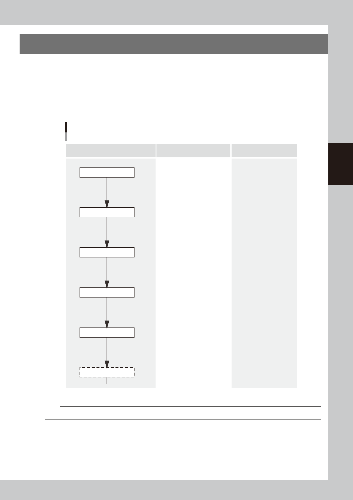
1. Flow of printing condition setting
The following diagram shows the flow of the condition setting (data setting) and the setup work necessary to
perform the printing with excellent quality.
•
Before starting the condition setting, it is necessary that the basic data input and the setup work have been completed.
•
The parameter change results after completion of the condition setting may slightly vary depending on the solder and/
or mask status.
•
It is recommended to first perform the test print with the default values and gradually narrow the conditions from the
test print results.
Printing condition setting
Contents of work Items to be set Related troubles
Setup work
Basic data input
・Alignment offsets X, Y, R
・Board size
・Mask information
・Squeegee type
・Edge clamp pressure
・Fiducial position coordinates
・Backup jig setting
・Board clamp status check
・Mark information check
Print deviation
Solder spread
Solder bridge
Print deviation
Solder enlargement
Solder chipping, mask remaining
Solder spread, solder bridge
Blur
Scraping trouble
Insufficient filling
・Squeegee pressure
・Squeegee speed
・Attack angle
・Board separation speed
・Board separation distance
・Alignment offset Z
・Solder supply interval
Solder chipping, mask remaining
Solder spread, solder bridge
・Cleaning interval
・Cleaning repeat
・Cleaning speed
Alignment offset
Cleaning conditions
Printed status check
Graphic alignment
Test print
Rolling
63300-N1-00
n
NOTE
For more details about work procedures and contents of each parameter, see the relevant sections of this manual.
3-2
3
Printing guide
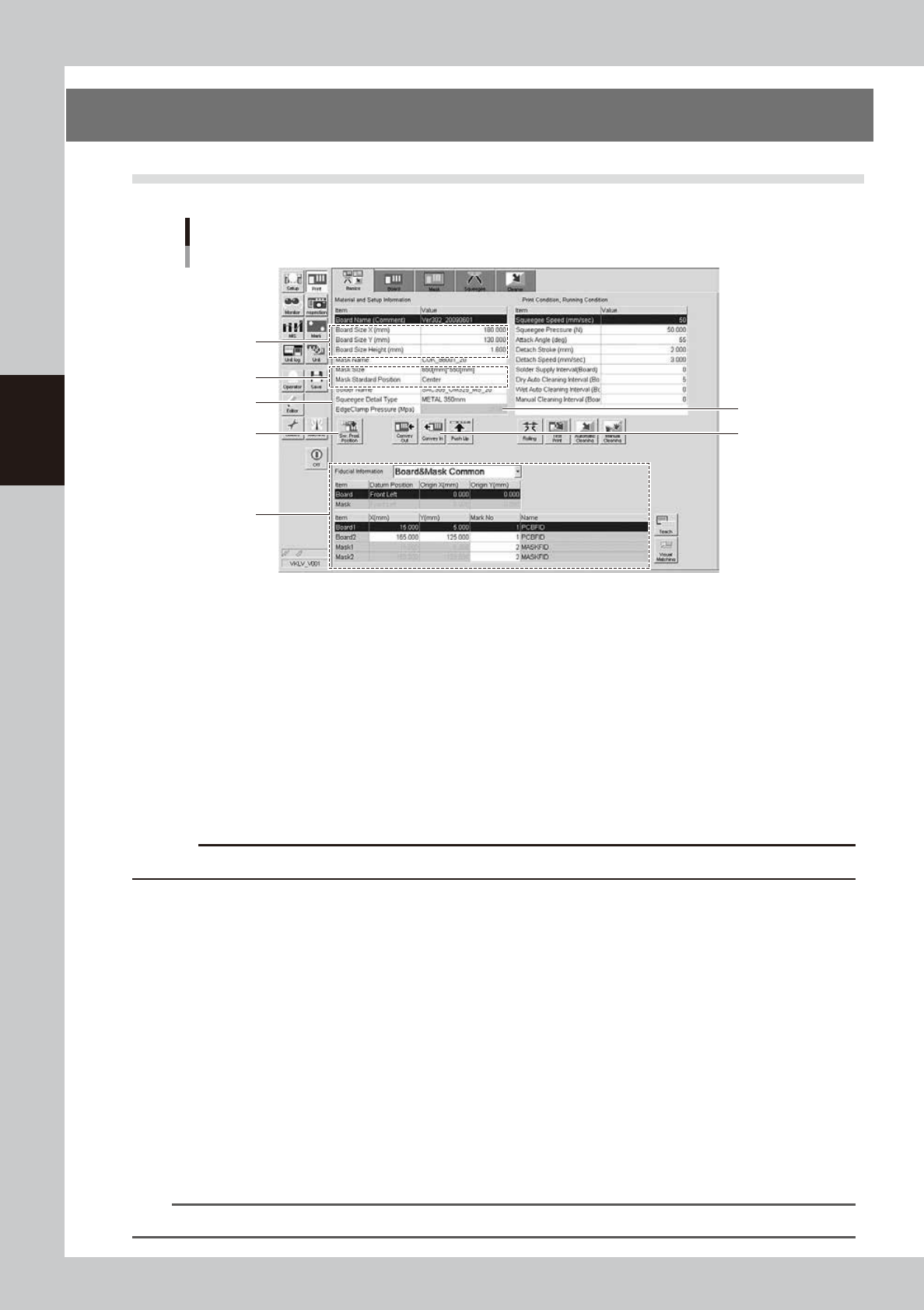
2. Data and condition setting
2.1 Material and setup information
Material and setup information
Step 1
Step 2
Step 3
Step 4
Step 9
Step 6
Step 5
64300-N1-00
1
Enter board size data.
Enter accurate size data (X, Y, height) of the board to be printed.
X : Sets the board clamp position.
Y : Sets the conveyor width.
Height : Sets the backup height.
2
Enter mask information.
1. Select a size of the mask to be used.
2. Select a mask standard position (standard position during the mask processing) (center or front
position).
c
CAUTION
In the YCP10, you cannot use the rear position. Always select either the center or front position.
3
Select a squeegee type.
Select a type and size of the squeegee to be used. Each squeegee type has the features described
below.
Urethane squeegee: If the squeegee pressure level is too high, the squeegee is deformed, causing the
solder to be scraped away too much.
Metal squeegee : This metal squeegee is not deformed by the squeegee pressure and is less affected
by the squeegee pressure.
4
Set the backup jigs.
1. Press the [SW. Prod. Position] button and select the setup item.
2. When rearranging the backup pins, select “Transfer Check Position”. The conveyor will move to the
setup position and the conveyor width will be automatically adjusted to match the board size.
3. When changing the whole matrix plate, select “Backup Setup”. The conveyor will move to the setup
position and the conveyor will be adjusted to the maximum width, allowing you to remove the matrix
plate.
n
NOTE
When removing the matrix plate, check for safety and then lift it straight up while holding firmly with both hands.