YCP10 Users_E.pdf - 第85页
3-9 3 Printing guide 3.2.2 Board edge offset n Function T his function sets a deviation in response position of the board detection sensor when detecting the board notch or edge shape so as to offset the board stop posit…
3-8
3
Printing guide
3.2 Board transfer
The YCP10 adapts a "servo transfer" that does not use the main stopper.
Unlike the transfer using the main stopper, since the positioning of the board stop position is performed by the
sensor response and servomotor RPM, the board stop position may vary depending on the transfer speed, board
material, surface treatment, shape, or weight.
In particular, when using bottom surface mounting boards, the board push-up may occur by the push-up
material during board clamp.
Therefore, functions to make the positioning of the board stop position stable are enhanced. Furthermore, in
addition to the functions to make the positioning stable, functions to make the transfer tact faster are also
provided. Make the settings appropriately according to the board.
c
CAUTION
Before starting the production, check the transfer sufficiently to make sure that any board push-up or drop does not
occur.
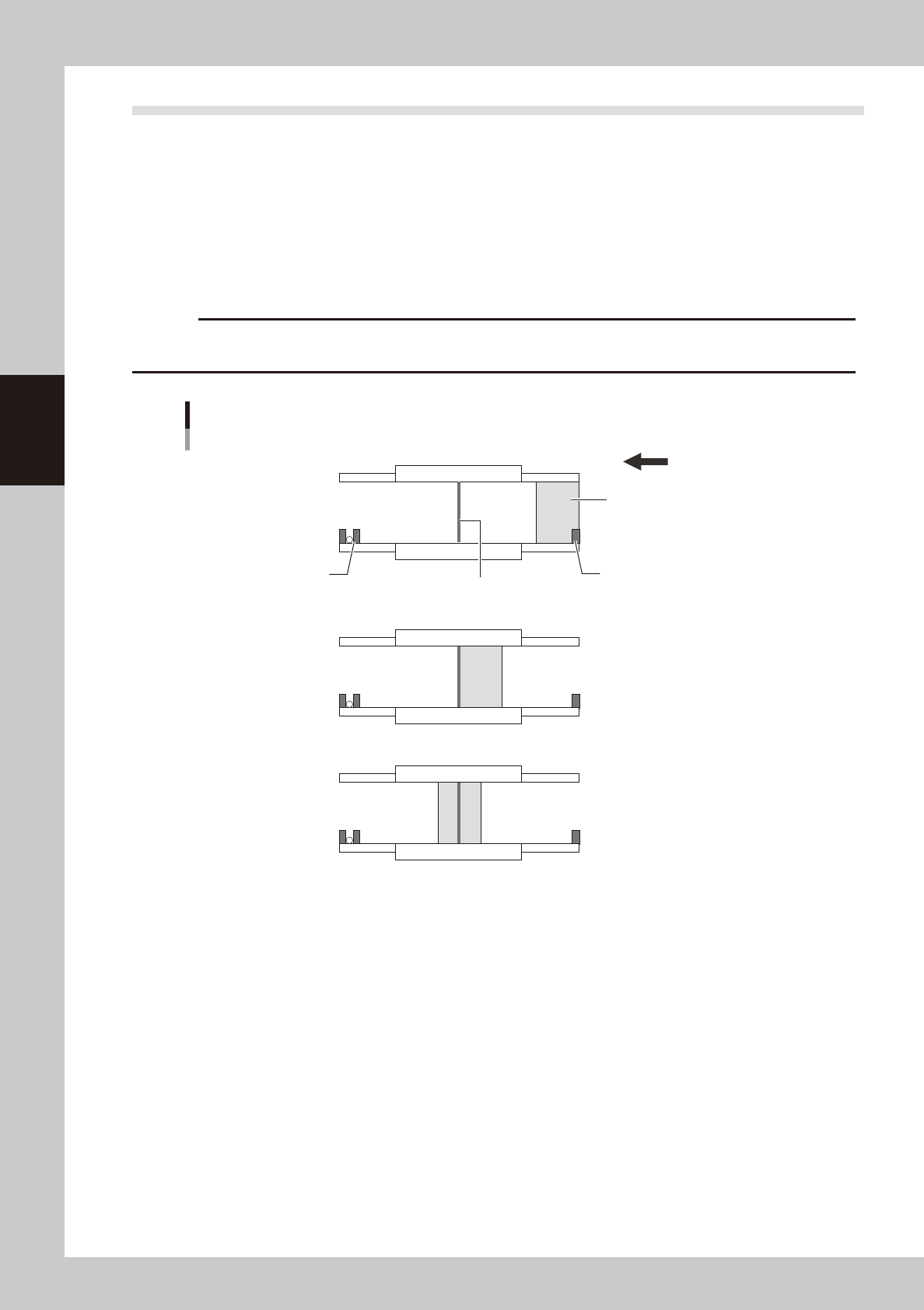
Board transfer using servo transfer
■ Transfer start
■ Board detection
■ Transfer completion
Exit sensor
Entrance sensor
Board
Printing position sensor
Transfer direction (right → left)
63307-N1-00
3.2.1 Transfer position check
n
Function
This function recognizes a desired mark by the board vision camera to correct the deviation amount of the transfer
position before board clamp.
This function increases the positioning accuracy of the board clamp.
n
Setting procedure
On the [Print]-[Board] tab screen, set "p. Carried Pos. Check" to "Enable" and set the values for related parameters.
(For details about how to set each parameter, see "3.1 Board marks and parameter setting" in Chapter 5.)
3-9
3
Printing guide
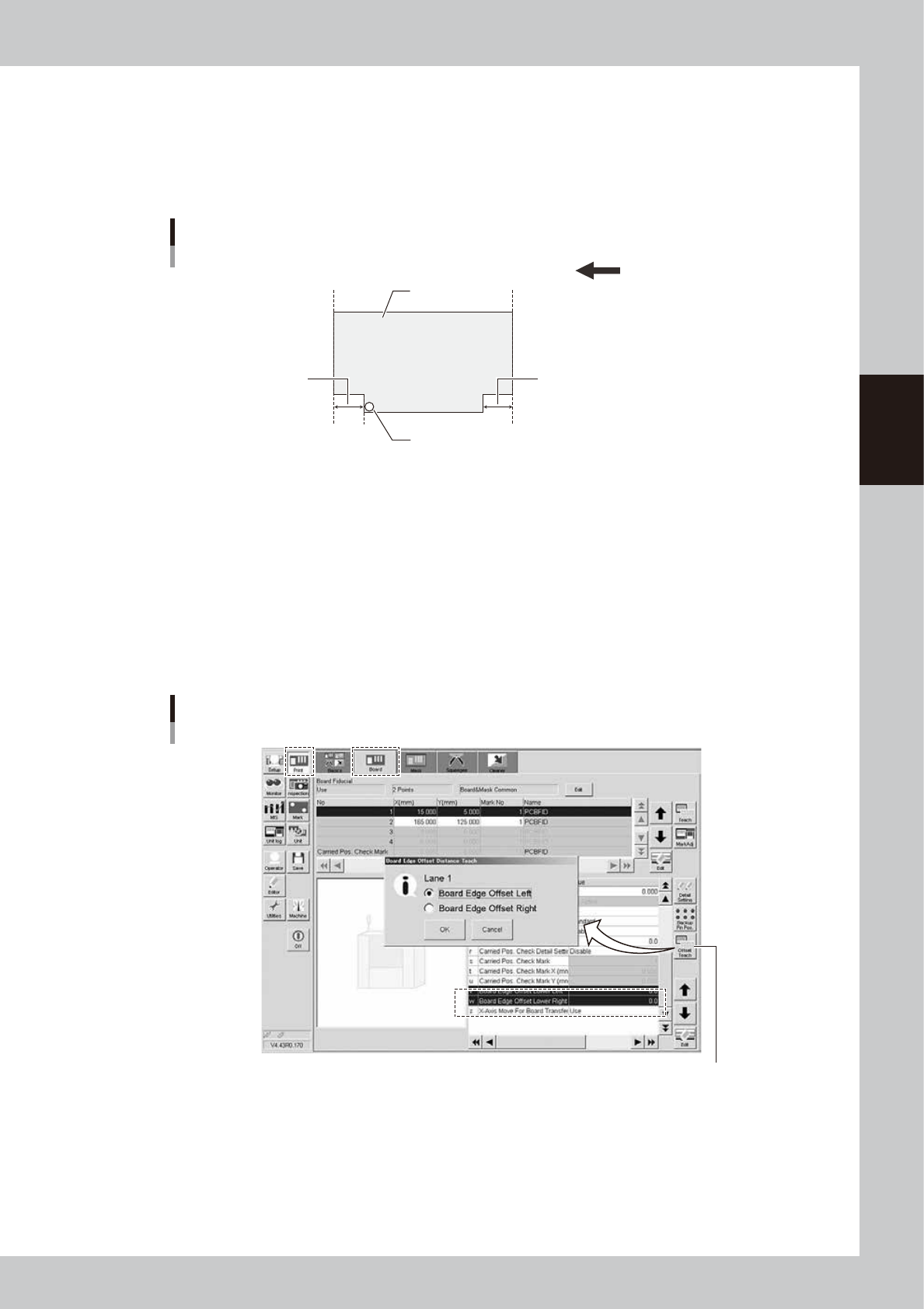
3.2.2 Board edge offset
n
Function
This function sets a deviation in response position of the board detection sensor when detecting the board notch or edge
shape so as to offset the board stop position.
Board edge offset
Transfer direction (right → left)
Board edge
Board
Sensor detection position
Board edge
Board edge offset Board edge offset
63308-N1-00
n
Setting procedure
When using the board edge offset, set the value to “v. Board Edge Offset Lower Left” or “w. Board Edge Offset Lower
Right” on the [Print]-[Board] tab screen through teaching using the [Offset Teach] button.
The initial value is "0.0". When the board edge offset function is not used, remain the initial value.
To use the board edge offset function, follow the steps below.
1. Press the [Offset Teach] button on the [Print]-[Board] tab screen.
2. The screen appears, allowing you to select a board edge offset you want to perform the teaching. Select a desired
board edge offset and press the [OK] button.
Board edge offset
[Offset Teach] button
[Offset Teach] button
64306-N1-10
3-10
3
Printing guide
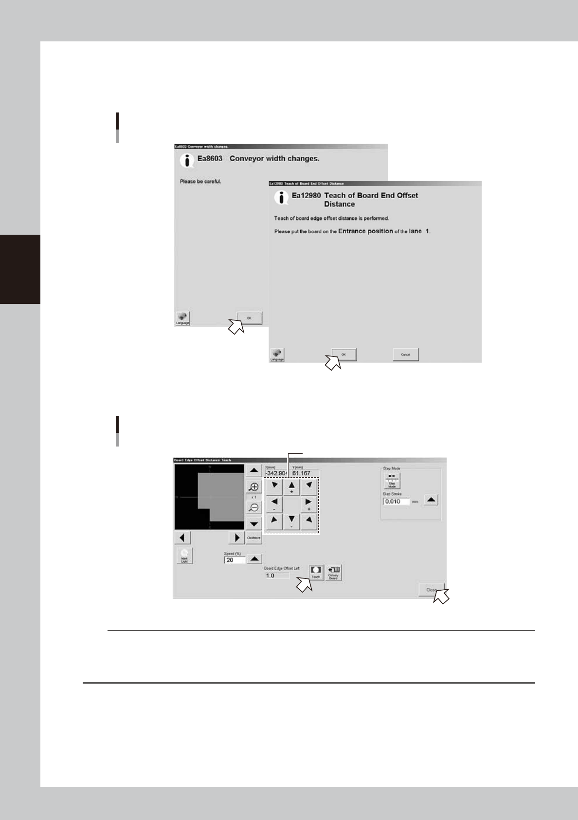
3. The message screen appears. Follow the instructions to set the board at the carry-in port, and then press the [OK]
button.
After the board has been transferred to the board clamp position, the board vision camera moves to the position where
the board detection sensor starts responding and the Teach screen will appear.
Board edge offset
Message screen
64307-N1-00
4. Operate the arrow buttons to display the board edge at the center of the screen, and then press the [Teach] button.
Board edge offset
Teach screen
Operate these buttons to display the board edge at the center.
64308-N1-00
TIP
When pressing the [Convey Board] button, the board is moved to the entrance or exit, and then it is transferred to the
detection sensor again.
When you want to perform the teaching again or make the check again with the values obtained from the teaching,
press this button to perform the operation again.