YCP10 Users_E.pdf - 第59页
1-18 1 Part names and functions 7. Ser vo-controlled axes The mechanical units of this machine move along the following ser vo-controlled axes. Other mechanical devices are driven by compressed air . Servo-controlled axi…
1-17
1
Part names and functions
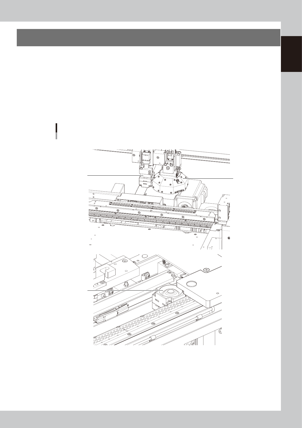
6. Vision camera unit
This machine is equipped with a "board vision camera" for recognizing fiducial marks and land patterns on
boards; and a "mask vision camera" for recognizing fiducial marks on the backside of masks (stencils) and
mask apertures. These cameras are also used as a teaching unit to perform teaching.
A "solder-print inspection camera" and a light are added to machines which have the optional solder-print
inspection function.
These cameras are used as a teaching unit to perform the teaching.
• The "board vision camera", "solder-print inspection camera (option)" and "lighting unit (option)" are installed on the
camera X-axis (CX-axis) and move only in the X direction. These cameras synchronize with the Y-axis to recognize
fiducial marks on the board surface.
• The "mask vision camera" is installed in front of the fixed conveyor rail and moves only in the X-direction. This camera
interlocks with the Y-axis to recognize the fiducial marks on the mask backside and mask apertures.
Vision camera unit
3
2
1
■ Board vision camera and solder-print inspection camera (Option)
■ Mask vision camera
63116-N1-00
1. Board vision camera, Lighting unit
This vision camera and lighting unit recognize the surface of a board clamped on the conveyor.
2. Mask vision camera, Lighting unit
This vision camera and lighting unit recognize the backside of a mask (stencil) clamped on the printing table.
3. Solder-print inspection camera (option), Lighting unit (option)
High-resolution, wide field-of-view camera and lighting unit installed in the YCP10 with an optional solder-print
inspection function. Refer to the separate "Option manual" for detailed information.
1-18
1
Part names and functions
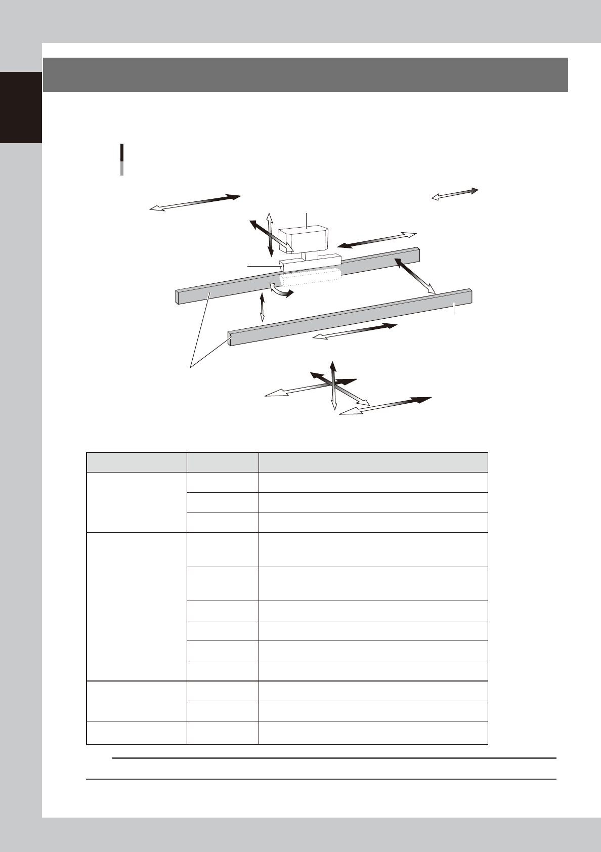
7. Servo-controlled axes
The mechanical units of this machine move along the following servo-controlled axes. Other mechanical
devices are driven by compressed air.
Servo-controlled axis configuration
Example of right flow
Squeegee head
SY-axis
SZ-axis
CX-axis
Camera unit
Plus direction
Minus direction
Squeegee
Conveyor rail
Board clamp conveyor
(board clamp table)
SR-axis
PU-axis
W-axis
MX-axis
CV-axis
X2-axis
X1-axis
Z-axis
Y-axis
63117-N1-00
n
Axis functions
Unit name Axis Function
Squeegee head
SY Moves the squeegee head parallel to the Y-axis.
SZ Moves the squeegee head vertically.
SR Adjusts the squeegee scraper angle. (3S head only)
Board clamp conveyor
(Board clamp table)
X1
Moves the board clamp table along the X-axis. This X1-axis
synchronizes with the X2-axis to function as R-axis during
operation.
X2
Moves the board clamp table along the X-axis. This X2-axis
synchronizes with the X1-axis to function as R-axis during
operation.
Y Moves the board clamp table along the Y-axis.
Z Moves the board clamp table vertically.
PU Raises and lowers the push-up plate.
MX Moves the mask camera along the X-axis.
Conveyor
W Changes the conveyor width.
CV Convey boards on the conveyor.
Camera unit CX
Moves the board camera and print-inspection camera along the
X-axis.
TIP
You can manually move each unit on the operation screen. See "4.1 "Move Axis" screen" in Chapter 7 for more details.

Chapter 2 Basic operations
This chapter explains how to start up the machine and power off, as well as basic menus displayed on the operation screen.
We recommend you read this chapter while actually operating the machine as instructed.
Contents
1.
Canceling emergency stop/clearing error 2-1
1.1 Canceling emergency stop 2-1
1.2 Clearing an error 2-2
1.3 Typical errors and troubleshooting 2-3
2. Starting and stopping the machine 2-7
2.1 Inspecting before operation 2-8
2.2 Starting the machine 2-9
2.3 Powering off the machine 2-11
3. Operation screen description 2-13
3.1 Basic configuration of operation screen 2-13
3.2 Various buttons and parameter input grids 2-14