YCP10 Users_E.pdf - 第140页
5-9 5 Cr eating and setting the data Y : Air conditioner interlock (option) When an optional temperature control unit is used, set whether or not to enable the interloc k mechanism that functions if an abnormal temperatu…
5-8
5
Creating and setting the data
Q: Board Press (option)
The board press unit holds down the board surface to correct the overall warp. Set this parameter to "Use" when using
the board press unit (option) or to "NotUse" when not using that unit. (This parameter is available only for machines
equipped with an optional board press unit.)
R: Press Timer (msec) (option)
When an optional board press unit is used, set the length of time to press on a board.
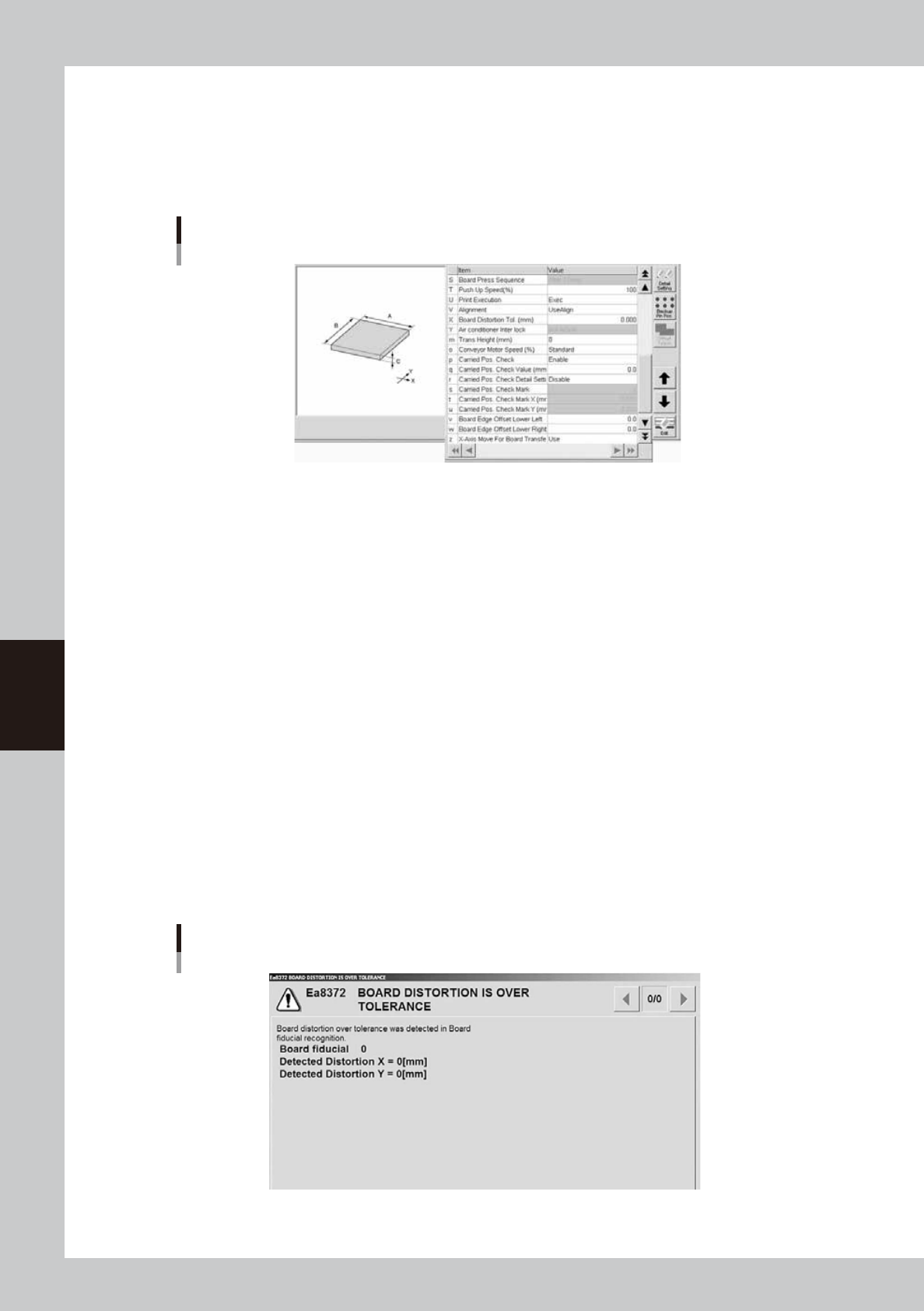
Board parameters (2)
64511-N1-00
S: Board Press Sequence (option)
When an optional board press unit is used, set whether to start pressing on a board before or after the edge clamp is
actuated.
T: Push Up Speed (%)
Specify the ascent/descent speeds for the push-up plate in percentage. Setting to "100" is acceptable in most cases, but
reduce it if you want to lessen the impact when the push-up jigs or pins move up against the board.
U: Print Execution
Select the operation mode from "Exec" or "Skip".
Exec : The machine performs solder printing.
Skip : The machine operates without applying any force.
V: Alignment
Select the processing method after fiducial mark recognition. Set to "UseAlign" in normal operation, and the machine
immediately stops when a mark recognition error occurs. When this is set to "IgnoreErr", the machine continues operation
even if a mark recognition error occurs.
X: Board Distortion Tol.
This parameter specifies the allowable distortion limit when checking the distortion component in the board fiducial
recognition position and local fiducial mark recognition positions on the board. The distortion check is not performed
when this parameter is set to "0.00".
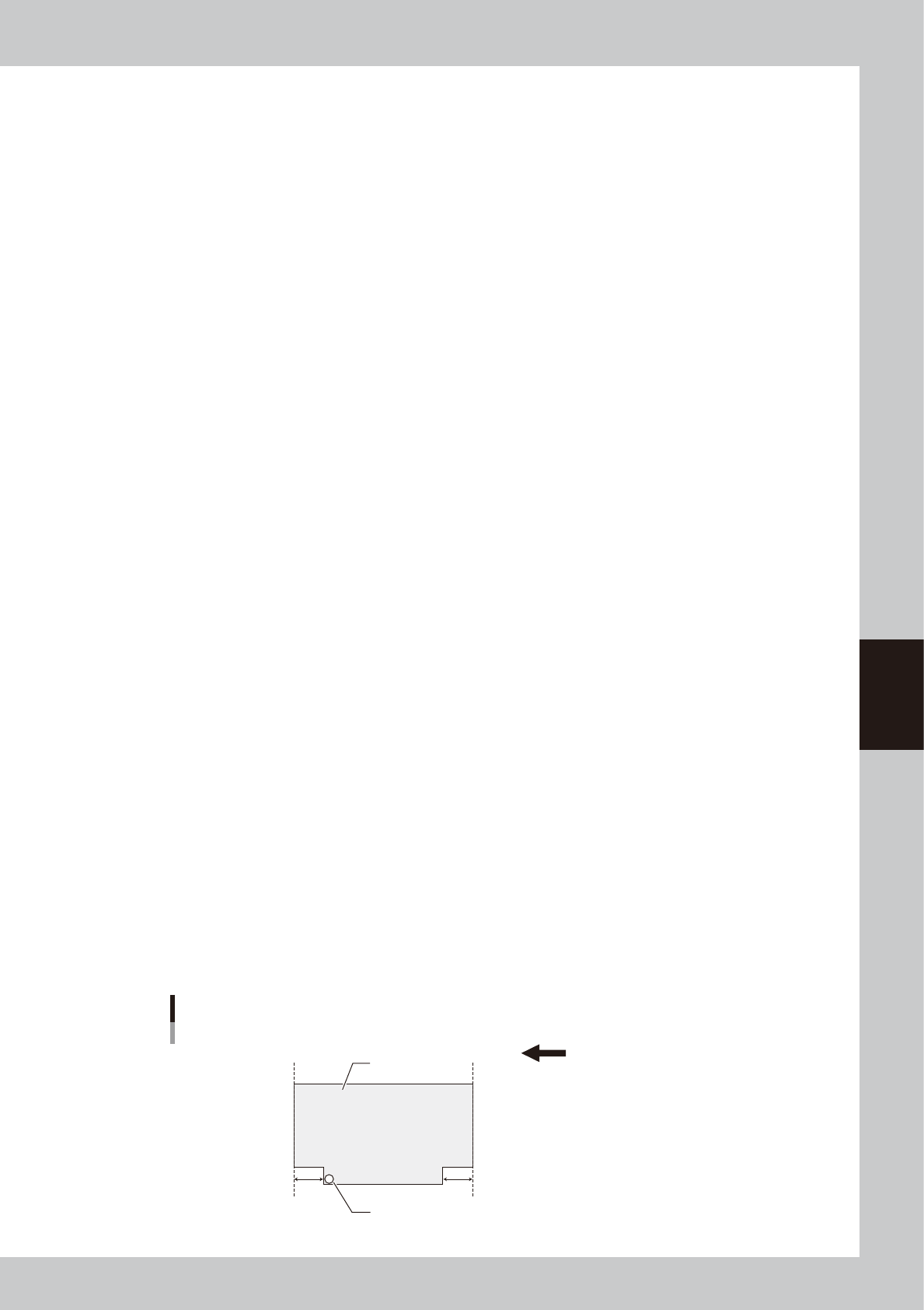
If the distortion component calculated by recognizing the board fiducial marks or local fiducial marks during automatic
operation exceeds the allowable limit specified here, an error message box appears as shown below and the machine
stops. After closing the error message box, you can select whether to print solder on the board or to convey the board out
without printing solder according to the screen that appears.
Error message for board distortion
64512-N1-00
5-9
5
Creating and setting the data
Y: Air conditioner interlock (option)
When an optional temperature control unit is used, set whether or not to enable the interlock mechanism that functions
if an abnormal temperature is detected.
m: Trans Height (mm)
After components are mounted, the machine permits the conveyor to carry out the board when the push-up unit is
lowered. If components have already been mounted on the reverse side of the board, the push-up unit must be lowered
sufficiently to avoid interference from push-up pins with those components. This parameter specifies the height of the
push-up unit at which the conveyor is allowed to carry out each type of board. Enter a numeric value ranging from 0 to
50 mm showing how many millimeters the transfer height is lowered from the height of the bottom surface mounted
component or board warpage.
When this parameter is set at "0 mm", the transfer height lowers to the maximum down height.
o: Conveyor Motor Speed (%)
Change this parameter setting if you want to change the conveyor motor speed (board transport speed). The conveyor
motor speed can be increased up to "Standard+50%" (150% of "Standard" speed) or decreased down to "Standard-90%"
(10% of "Standard" speed) in 10% steps.
p: Carried Pos. Check
Enables/disables the conveyance position check. The standard setting is "Enable". When enabled, the board's position is
verified by the board vision camera which checks the board's 1st fiducial mark before the conveyed board is secured.
q: Carried Pos. Check Value (mm)
Enter a value that is used to judge whether or not the board position is corrected when checking the transfer position.
A value ranging from 0.0 to 5.0 mm can be entered.
If the mark position is beyond the set range, the board is moved by the mark shift amount.
(This parameter is enabled
only if the "o: Carried Pos. Check" item is set as "Enabled".)
r: Carried Pos. Detail Setting
Make this setting when a mark different from the fiducial mark or first point is used to check the transfer position. The
standard setting is "Disabled". (This parameter is enabled only if the "o: Carried Pos. Check" item is set as "Enabled".)
s: Carried Pos. Check Mark
Inputs the mark No. used for the conveyance position check detailed setting. The input value setting range is 0 to 128.
The recognition status of the mark used for the conveyance position check must be verified by performing a mark position
check, and the mark must then be registered in the mark information. (This parameter is enabled only if the "r: Carried
Pos. Detail Setting" item is set as "Enabled".)
t: Carried Pos. Check Mark X (mm)
Inputs the X-coordinate of the conveyance position check mark. (This parameter is enabled only if the "r: Carried Pos.
Detail Setting" item is set as "Enabled".)
u: Carried Pos. Check Mark Y (mm)
Inputs the Y-coordinate of the conveyance position check mark. (This parameter is enabled only if the "r: Carried Pos.
Detail Setting" item is set as "Enabled".)
v: Board Edge Offset Lower Left, w: Board Edge Offset Lower Right
If the board edge cannot be detected by the board detection sensor due to board shape, press the [Offset Teach] button to
enter a distance from the board edge to the sensor detection position through teaching. The initial value is "0.0". When
the board edge offset function is not used, remain the initial value. (For details about teaching, see "3.2.2 Board edge
offset" in Chapter 3.)
Board edge offset
Board edge transfer direction (right → left)
Board edge
Board
Sensor detection position
Board edge
v w
63532-N1-00

5-10
5
Creating and setting the data
z: X-Axis Move For Board Transfer
This function moves the print table (X-axis) so as to minimize the time loss associated with the movement when
delivering the board between the upstream and downstream machines. Select either "Use" or "Not Use".
Use: The print table (X-axis) moves to the soft limit when delivering the board between the upstream and
downstream machines.
Not Use: The print table (X-axis) does not move to the soft limit when delivering the board between the upstream and
downstream machines.
To reduce the tact time, select this setting.
c
CAUTION
This function is enabled only when the board size X is 100.0 mm or more.
When the board size X is less than 100.0 mm, this function performs the operation with "Not Use" setting regardless of
the setting.