YCP10 Users_E.pdf - 第138页
5-7 5 Cr eating and setting the data F: Board Datum Position Set the reference position on a board select by selecting from "Center", "F ront Center", "Rear Center", "Front Left", …
5-6
5
Creating and setting the data
3: Fiducial Position
This parameter sets whether to share the local fiducial mark position with the board and the mask. Pressing the [Edit]
button at the upper right displays the screen shown above. Select "Board&Mask Individual" or "Board&Mask Common"
from the Fiducial Position drop-down list.
When "Board&Mask Individual" is selected, the Fiducial Position, Fiducial Type and Standard Position parameters can be
set separately on the board and the mask.
When "Board&Mask Common" is selected, the Fiducial Position, Fiducial Type and Standard Position parameters are
jointly shared by the board and mask. A confirmation message box appears when you select "Board&Mask Common".
Pressing the [OK] button in the message box will copy the board fiducial mark setting (Fiducial Position, Fiducial Type
and Standard Position parameters) into the mask fiducial mark setting.
n
NOTE
If the Fiducial Position, Fiducial Type and/or Standard Position parameter are changed on the [Board] tab or [Mask]
tab by editing or teaching, the change is automatically applied to the other items.
4: X, Y (mm)
Enter the XY coordinates of each fiducial mark relative to the board origin in millimeters. You can perform teaching with
the [Teach] button. Enter the center coordinates in the case of circular, square and triangular marks.
TIP
For details on teaching, see "1. Teach and trace" in chapter 7.
5: Mark No.
Enter the mark No. of each fiducial mark. (Mark No. should be registered in advance on the Mark screen.)
6: Name
When the mark No. is entered, the corresponding name automatically appears here. (Mark name should be registered in
advance on the Mark screen.)
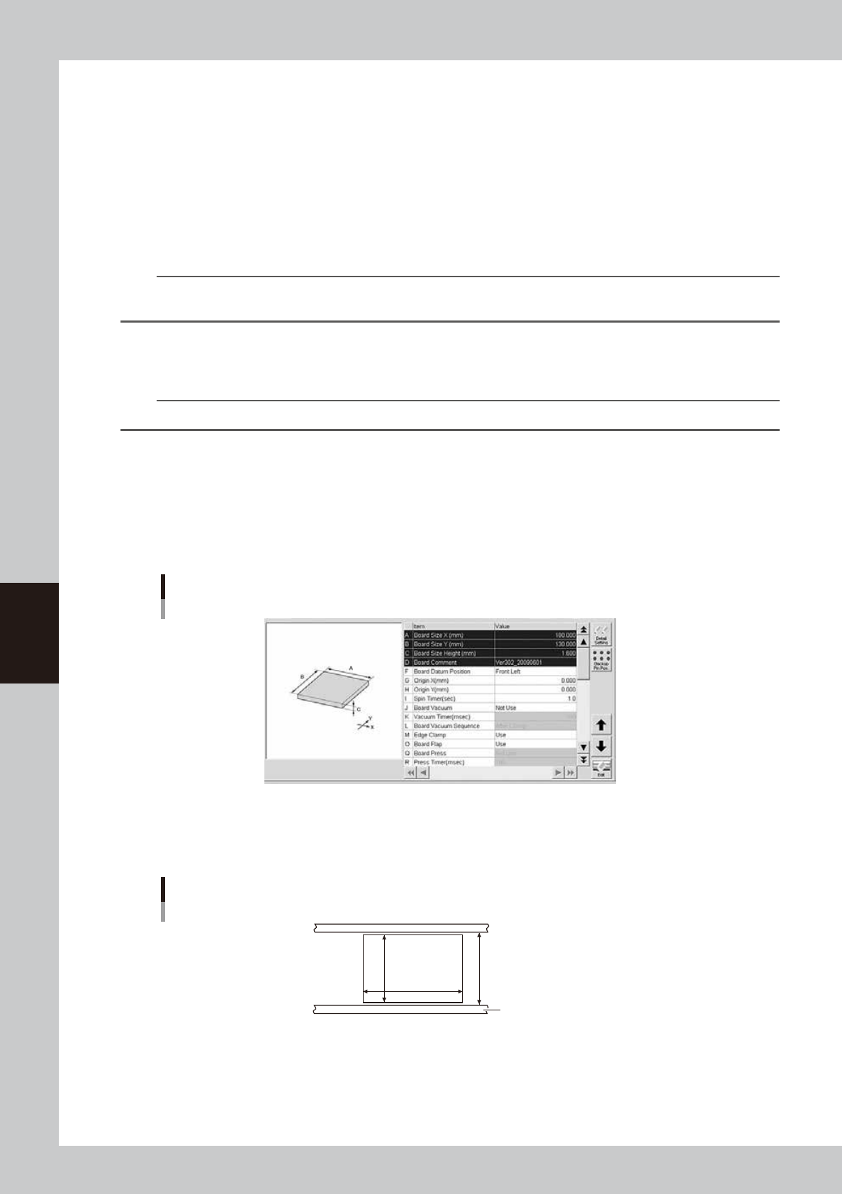
7: Board parameters
Board parameters (1)
64510-N1-00
A, B: Board Size X, Y (mm)
Enter the board size (mm) in the X direction (board transport direction) and in the Y direction. The conveyor width
(W-axis) is adjusted to the Y dimension + 0.5 mm when the board is clamped during automatic operation.
Board Size X, Y
Board
Conveyor rail
X [mm]
W=(Y+0.5mm)
Y [mm]
63502-N1-00
C: Board Size Height (mm)
Enter the board thickness (mm).
D: Board Comment
Enter a comment on the board. You can leave this field blank.
5-7
5
Creating and setting the data
F: Board Datum Position
Set the reference position on a board select by selecting from "Center", "Front Center", "Rear Center", "Front Left", "Front
Right, "Rear Left" or "Rear Right" as shown below. On standard machines, this is set to "Front Left" as the default. All
coordinate positions on a board are specified relative to the "Board Datum Position" coordinates.
Board Datum Position
Board Datum Position
Board
63503-N1-00
TIP
The board has "Origin XY", "Fiducial (Mark)" and "Board Check Position" parameters as its setting positions .
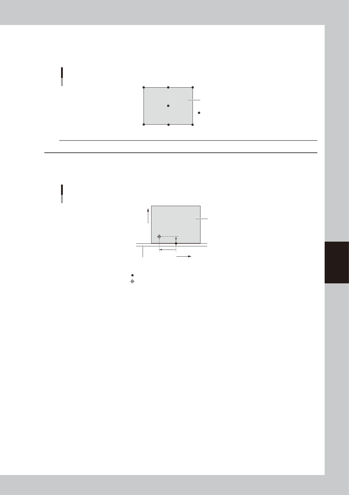
G, H: Origin X, Y (mm)
If the fiducial mark on a board uses an origin different from the Board Datum Position, set the positional offset (mm) here
as the Origin XY.
Board Datum Position and Board origin
X-
X+
+Y
+Y
Fixed (front) conveyor rail
Board
Board Datum Position (Front Center)
Board origin
63504-N1-00
I: Spin Timer (sec)
Set to "1" second for normal shape boards. If specially configured boards (for example, boards with cutouts or through-
holes) are used and the conveyor exit sensor cannot detect them correctly, try setting this timer between 0.0 and 9.9
seconds. The conveyor motor continues turning for the specified time even after the board sensor turns off.
J: Board Vacuum
This parameter is enabled only for machines equipped with an optional vacuum gripper. Set to "NotUse" in most cases.
When curved boards or thin boards are to be printed, setting this parameter to "Use" actuates the vacuum gripper to fix
the board from the backside. When this parameter is set to "Use", also specify an appropriate time (msec) in the "Vacuum
Timer" and "Board Vacuum Sequence" parameters.
K: Vacuum Timer (msec)
When the "Board Vacuum" parameter is set to "Use", set the timer (msec) here to initiate the next action after the push-up
plate has moved up. This parameter is enabled only for machines equipped with an optional vacuum gripper.
L: Board Vacuum Sequence
This parameter is enabled only when the "Board Vacuum" parameter is set to "Use". Set to "Before Clamp" to turn on the
vacuum gripper before clamping a board. Set to "After Clamp" to turn on the vacuum gripper after clamping a board.
M: Edge clamp
The edge clamps secure the board in the printing position by laterally pushing on the board edge. Set this parameter to
"Use" in most cases. If printing on boards which cannot be clamped from the edge such as thin ceramic boards, set to
"NotUse" and use a vacuum board gripper instead.
O: Board flap
Set whether to use the board flap that presses on the board edge from above.
Usually, set this parameter to "Use". Using the board flap corrects the upward warp of a board that might occur when
clamped.
5-8
5
Creating and setting the data
Q: Board Press (option)
The board press unit holds down the board surface to correct the overall warp. Set this parameter to "Use" when using
the board press unit (option) or to "NotUse" when not using that unit. (This parameter is available only for machines
equipped with an optional board press unit.)
R: Press Timer (msec) (option)
When an optional board press unit is used, set the length of time to press on a board.
Board parameters (2)
64511-N1-00
S: Board Press Sequence (option)
When an optional board press unit is used, set whether to start pressing on a board before or after the edge clamp is
actuated.
T: Push Up Speed (%)
Specify the ascent/descent speeds for the push-up plate in percentage. Setting to "100" is acceptable in most cases, but
reduce it if you want to lessen the impact when the push-up jigs or pins move up against the board.
U: Print Execution
Select the operation mode from "Exec" or "Skip".
Exec : The machine performs solder printing.
Skip : The machine operates without applying any force.
V: Alignment
Select the processing method after fiducial mark recognition. Set to "UseAlign" in normal operation, and the machine
immediately stops when a mark recognition error occurs. When this is set to "IgnoreErr", the machine continues operation
even if a mark recognition error occurs.
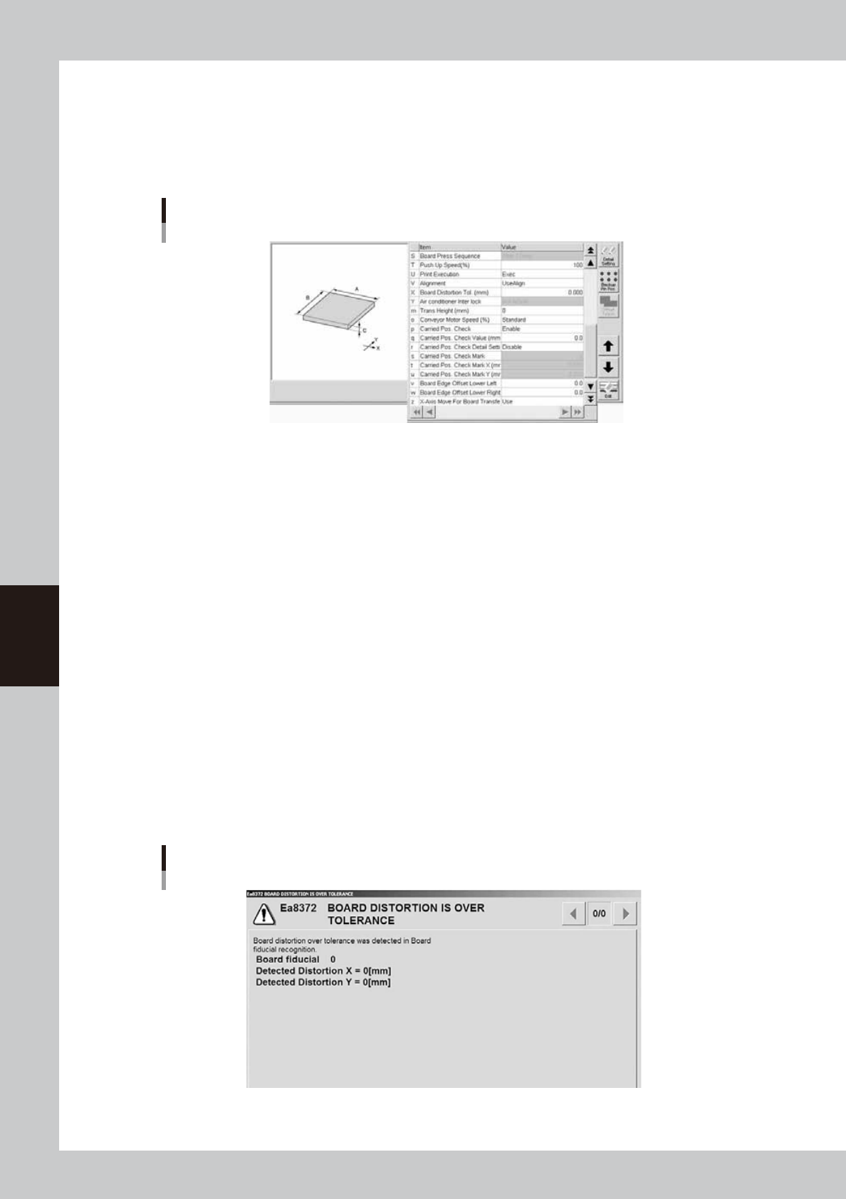
X: Board Distortion Tol.
This parameter specifies the allowable distortion limit when checking the distortion component in the board fiducial
recognition position and local fiducial mark recognition positions on the board. The distortion check is not performed
when this parameter is set to "0.00".
If the distortion component calculated by recognizing the board fiducial marks or local fiducial marks during automatic
operation exceeds the allowable limit specified here, an error message box appears as shown below and the machine
stops. After closing the error message box, you can select whether to print solder on the board or to convey the board out
without printing solder according to the screen that appears.
Error message for board distortion
64512-N1-00