YCP10 Users_E.pdf - 第45页
1-4 1 Part names and functions 2. Operation panels and data input units Operation panel buttons and operation display used to operate this machine or input the data are installed. This section describes the functions of …
1-3
1
Part names and functions
n
Main pressure regulator, air pressure supply/shutoff switch
Regulates the air pressure supplied to the machine.
n
Right panel at lower portion on front
Circuit breaker for each unit and power connection terminal are located inside the panel.
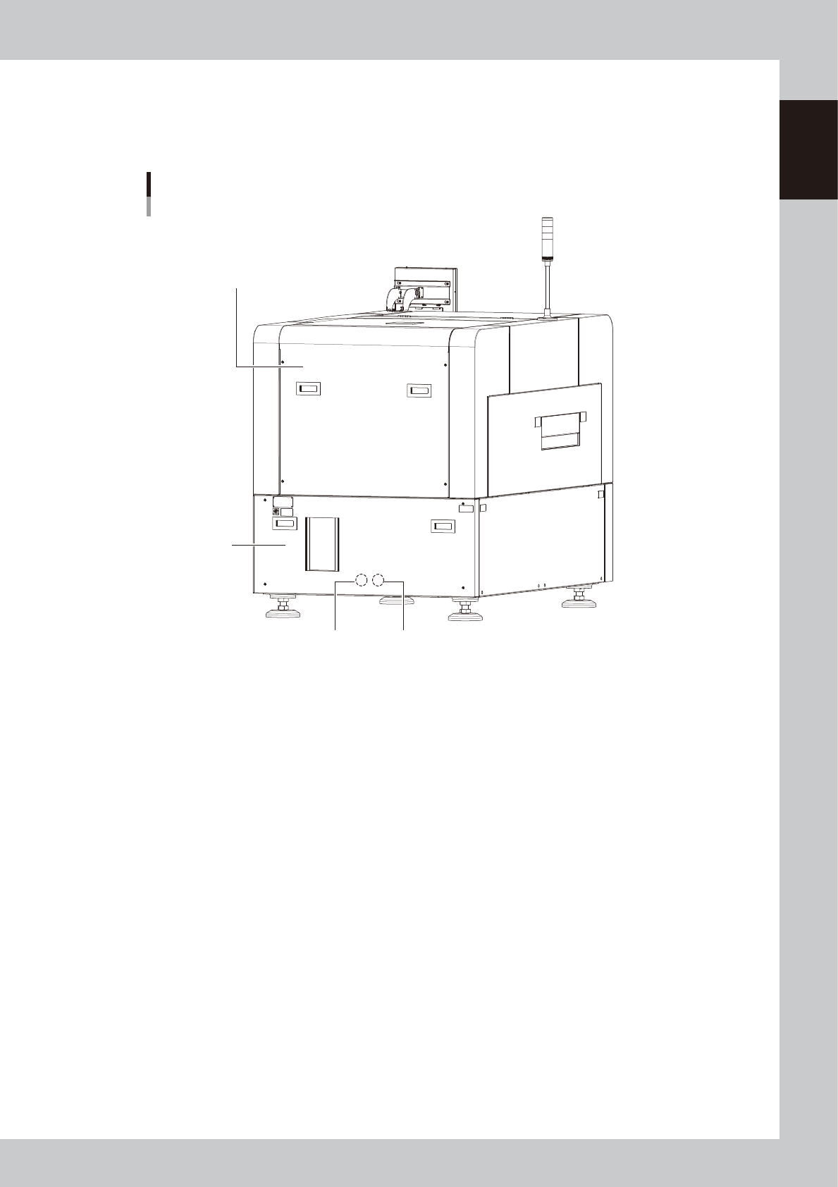
YCP 10main unit
Rear view
Previous Interface Next Interface
Rear lower panel
Rear cover
63102-N1-00
n
Rear cover
Be sure to close the cover during operation.
n
Rear lower panel
System motherboard, power supply board, servo control board, and vision board are assembled inside the panel.
n
I/O signal connectors (behind rear lower panel)
This connector is intended to connect the upstream machine and downstream machine. For details, see Appendix 1.3,
"Input/output connector between machines".
1-4
1
Part names and functions
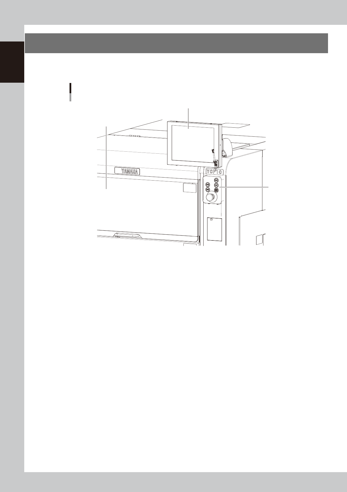
2. Operation panels and data input units
Operation panel buttons and operation display used to operate this machine or input the data are installed.
This section describes the functions of these units.
Operation panel and data input unit
Operation panel
buttons
Operation display
Upper door (safety cover)
63103-N1-00
1-5
1
Part names and functions
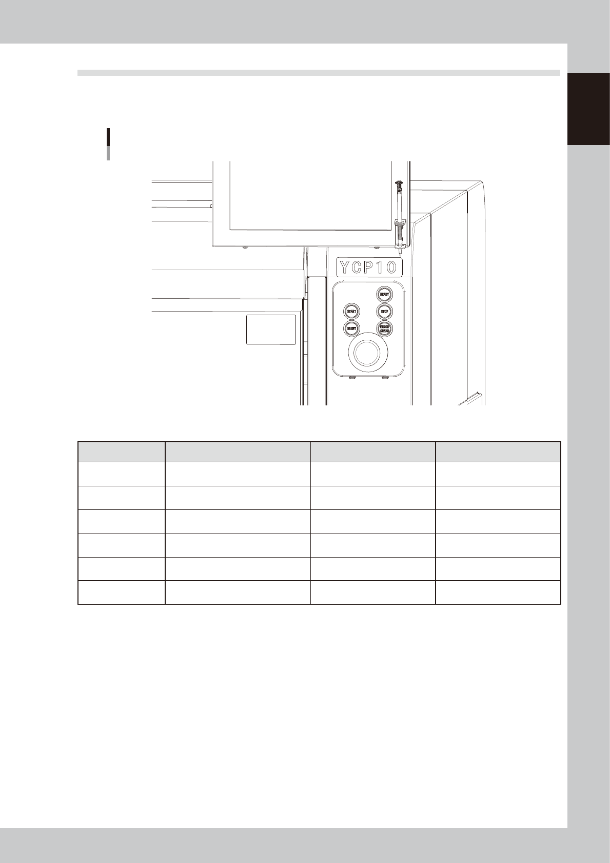
2.1 Operation panel buttons
The operation panel buttons are provided on the front and rear of the machine to run major commands
frequently used to operate the machine. Each button is lit while turned on. The colors used for the operation
panel are the same as those specified for the signal light (signal tower).
Operation panel buttons
63104-N1-00
n
Operation panel button functions
Button name Use the button to: OFF ON
READY
Release emergency stop and turn the
servo on.
• SERVO OFF
(Motor power OFF)
• SERVO ON
(Motor power ON)
RESET
Stop automatic operation and return to
standby for board production.
• Machine is in normal operation
or stopped.
• Machine has been reset.
START (green)
Perform operation according to board
data.
• Machine is stopped. • Machine is in normal operation.
STOP (Red / White)
Interrupt automatic operation. (Press
START to resume operation.)
• Machine is in normal operation. • Error occurred.
ERROR CLEAR
(Yellow / Blue)
Stop buzzer sound and clear error
screen.
• Machine is in normal operation. • Error occurred.
EMERGENCY STOP
Trigger emergency stop. Turn to the
right to release it.