YCP10 Users_E.pdf - 第48页
1-7 1 Part names and functions 3. Printing section This machine uses a printing pressure feedback head and a highly rigid printing table to perfor m solder paste printing at high speeds yet with high accuracy . 3.1 Squee…
1-6
1
Part names and functions
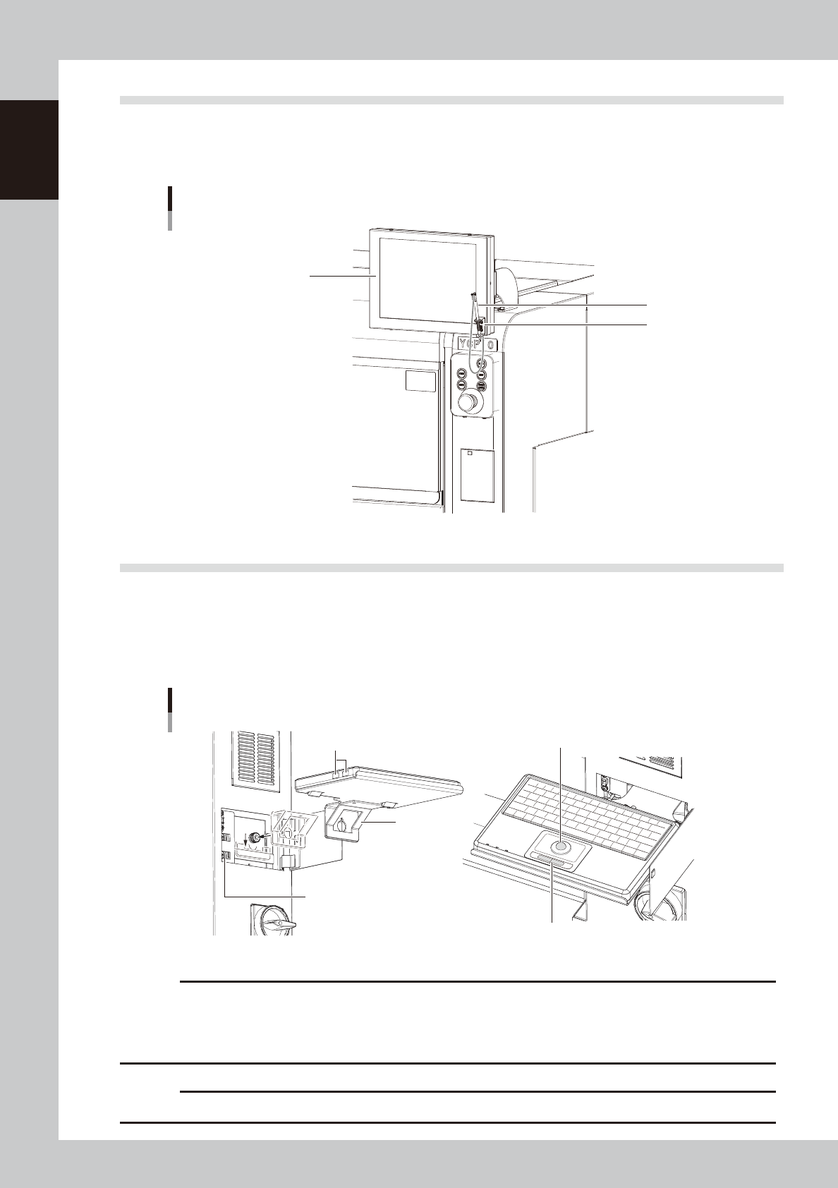
2.2 Operation display screen
Machine operation and data editing procedures are performed at the operation display screen (touch-panel
specifications). A touch pen is used to select the onscreen buttons and parameter items. Be sure to return the
touch pen to its holder when it is not in use.
Touch screen (option)
Operation display screen
(Touch-panel)
Holder
Touch pen
63105-N1-00
2.3 Keyboard (option)
An optional keyboard for operation and data editing, etc., can be added to the machine's configuration if
desired. The keyboard's track-ball is used to move the cursor to the desired onscreen buttons and parameter
items which are then selected by pressing the left-click button (right-clicking is not available).
When using the keyboard, install the bracket on this machine and connect the USB terminal of the keyboard to
the USB port on this machine.
Keyboard
Bracket
These USB ports are not allowed to use.
USB port for keyboard connection
Track-ball
Left/right button
63106-N1-00
c
CAUTION
The USB port shown in the illustration is for the keyboard only. (Only keyboards which do not require a -101 dedicated
driver are supported.) Do not connect other USB devices to this port.
Moreover, connecting 2 or more keyboards will disable exclusive access control, and therefore stop keyboard
operation.
c
CAUTION
Do not use the USB ports of the keyboard. The USB port may not operate correctly due to insufficient power.
1-7
1
Part names and functions
3. Printing section
This machine uses a printing pressure feedback head and a highly rigid printing table to perform solder
paste printing at high speeds yet with high accuracy.
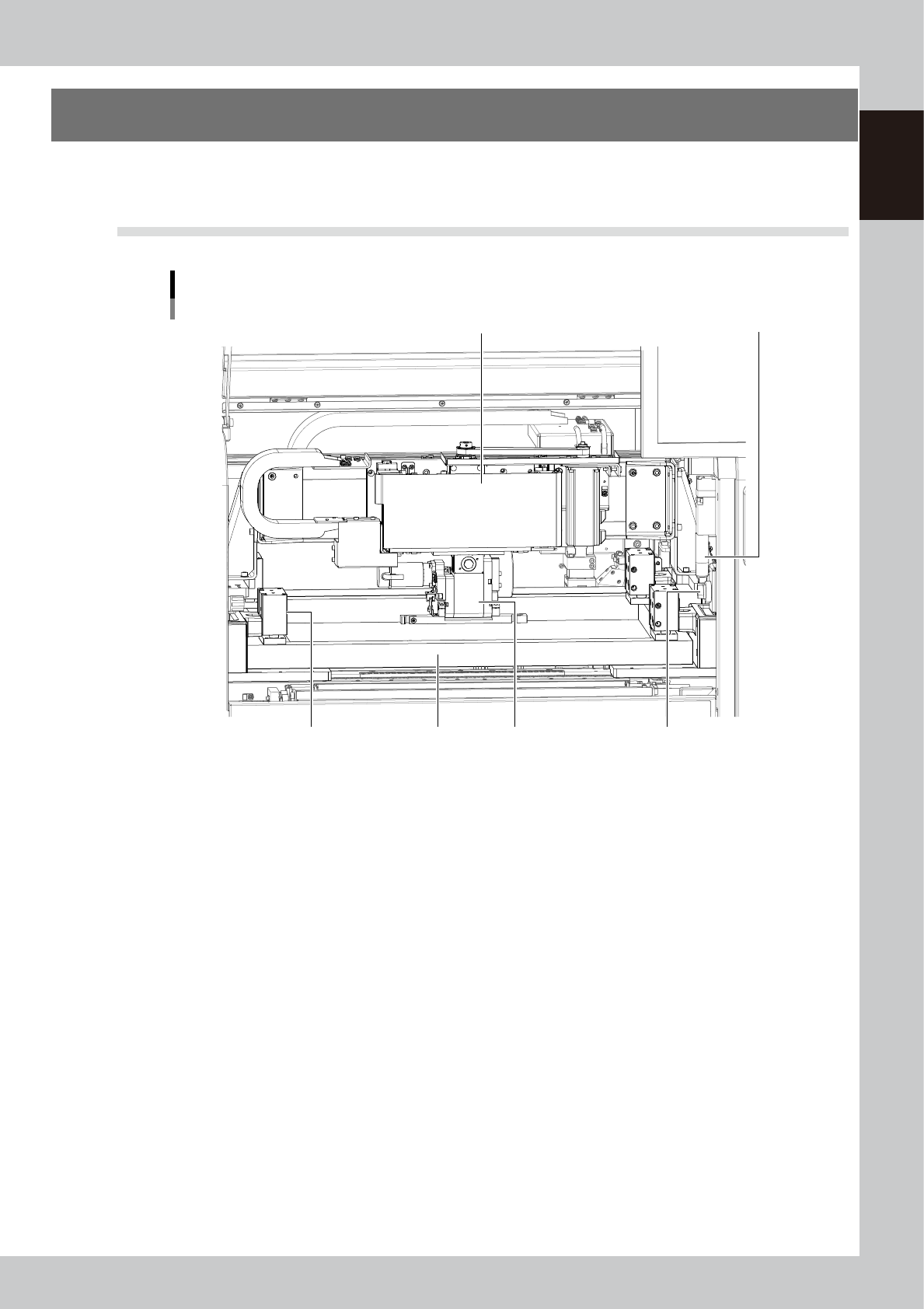
3.1 Squeegee head and printing table
Squeegee head and printing table
1
23
6
4
5
63107-N1-00
1. Squeegee head
Moves the squeegee vertically (along the SZ-axis) and forwards or backwards (along the SY-axis ). The 3S squeegee head
rotates slightly even in the R direction.
2. Squeegee holder
The squeegee can be easily mounted in this squeegee holder with two screws.
3. Mask clamp
Clamps a mask frame on the printing table. There are two clamps each on the left and right sides (a total of 4 clamps).
When using a small mask, attach the special adaptor at two locations on the rear.
4. Mask clamp switch
Turn this switch CCW or CW to release or clamp the mask.
5. Mask (prepared by user)
Various types of masks (stencils) with different frame sizes can be used by just changing the position of the stopper pin.
For information about the mask frame sizes and stopper pin positions, see "7.1 Mask size and mask stopper pin position"
in Chapter 4.
6. Handle
Use the handles on both sides to move the squeegee head forwards or backwards by hand during servo-off. Never move
the squeegee head by pushing it or the squeegee.
1-8
1
Part names and functions
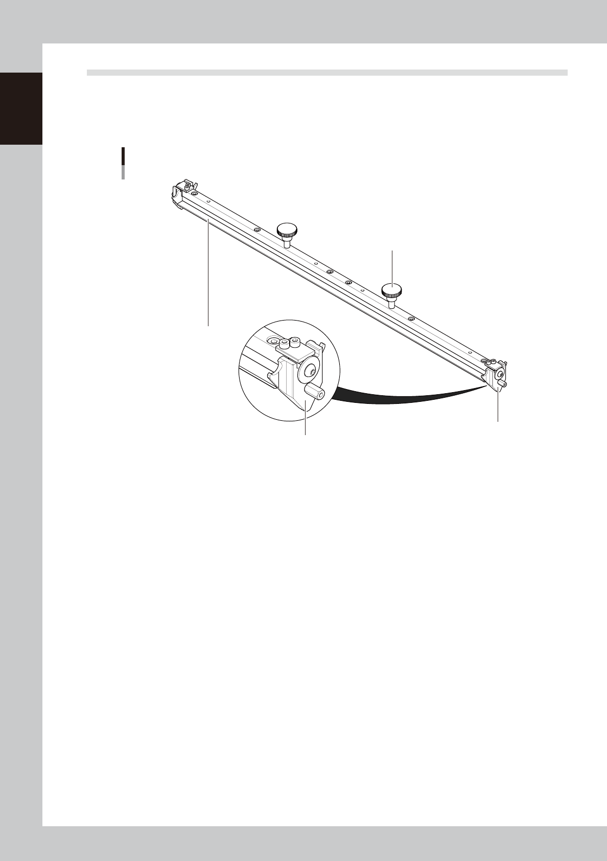
3.2 3S squeegee
This 3S squeegee allows you to adjust the squeegee scraper contact angle as needed. Since the same scraper
surface is used for solder printing in the forward and backward directions there will be less solder wasted.
Metal or urethane scraper 3S squeegees with a length of 250 mm, 300 mm, 350 mm, 400 mm, 440 mm or 530
mm are supplied with the machine according to your order.
3S squeegee
1
2
3
3
63108-N1-00
1. Scraper
Prints solder patterns on a board while uniformly scraping solder paste placed on the mask. The 3S squeegee has
double-edge scrapers made of urethane or metal.
2. Mount knob
Tighten these mount knobs to install the squeegee on the squeegee holder.
3. Side plate
Prevents solder paste on the mask from spreading beyond the squeegee width. This side plate contains a snap-in
mechanism which allows you to easily detach or attach the side plate during the squeegee cleaning.