YCP10 Users_E.pdf - 第175页
5-44 5 Cr eating and setting the data 3 T each the coordinates for gr aphic alignment. 1. Press the [T each] button to open the teach window for graphic alignment. 2. Position the cursor on the first coordinates and pres…
5-43
5
Creating and setting the data
8. Graphic alignment
When finished creating board data and necessary mark data, you should check to see whether the mask
apertures are aligned with the land patterns on the board, and correct any offsets (positional shifts) as
needed.
n
NOTE
When fiducial marks on the board and mask frame are used, their positions are automatically aligned by vision
recognition, so you can omit "graphic alignment". However, when the fiducial mark positions were defined by
teaching or when the mask aperture shapes are not identical with the land pattern shapes, then position alignment
may not be accurate if only using vision recognition. In those cases, the graphic alignment function allows you to
make position alignment easily and accurately.
l
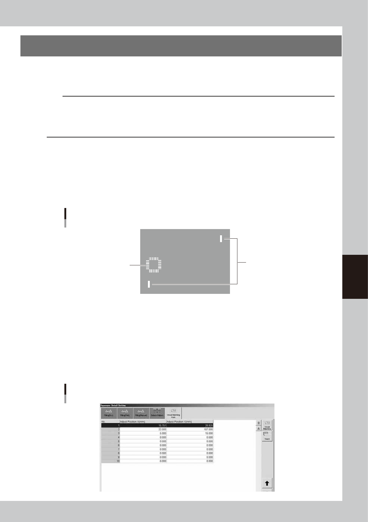
Coordinates used for graphic alignment
1. If the center deviation and rotational deviation exist, specify two diagonal points as shown below.
2. If you want to make alignments at a particular point other than the above two diagonal points, then specify only that
one point after adjusting the rotational deviation of the entire board by specifying the two diagonal points. If two
particular points are specified in this case, the rotational component that has already been adjusted will change, so use
caution.
The coordinates to be specified for graphic alignment should be measured in advance, or if the coordinate data (design
data) is available, make a note of the coordinates in advance.
Specified coordinates for graphic alignment
Specify two diagonal points.
2
1
3
After offset amount is updated
63529-N1-00
1
Load a board on the conveyor.
1. Press the [Setup] button and select the [Setup] tab.
2. Press the [Conveyor In] button and follow the message on the screen to load the board.
2
Temporarily enter the coordinates used for graphic alignment.
1. Press the [Print] button, open the [Squeegee] tab, and press the [Detail Setting] button.
2. Open the [Visual Matching Point] tab.
3. In the "Adjust Position X" and "Adjust Position Y" fields, enter the coordinates that have been
measured in advance.
Temporarily entering the coordinates for graphic alignment
64538-N1-00
5-44
5
Creating and setting the data
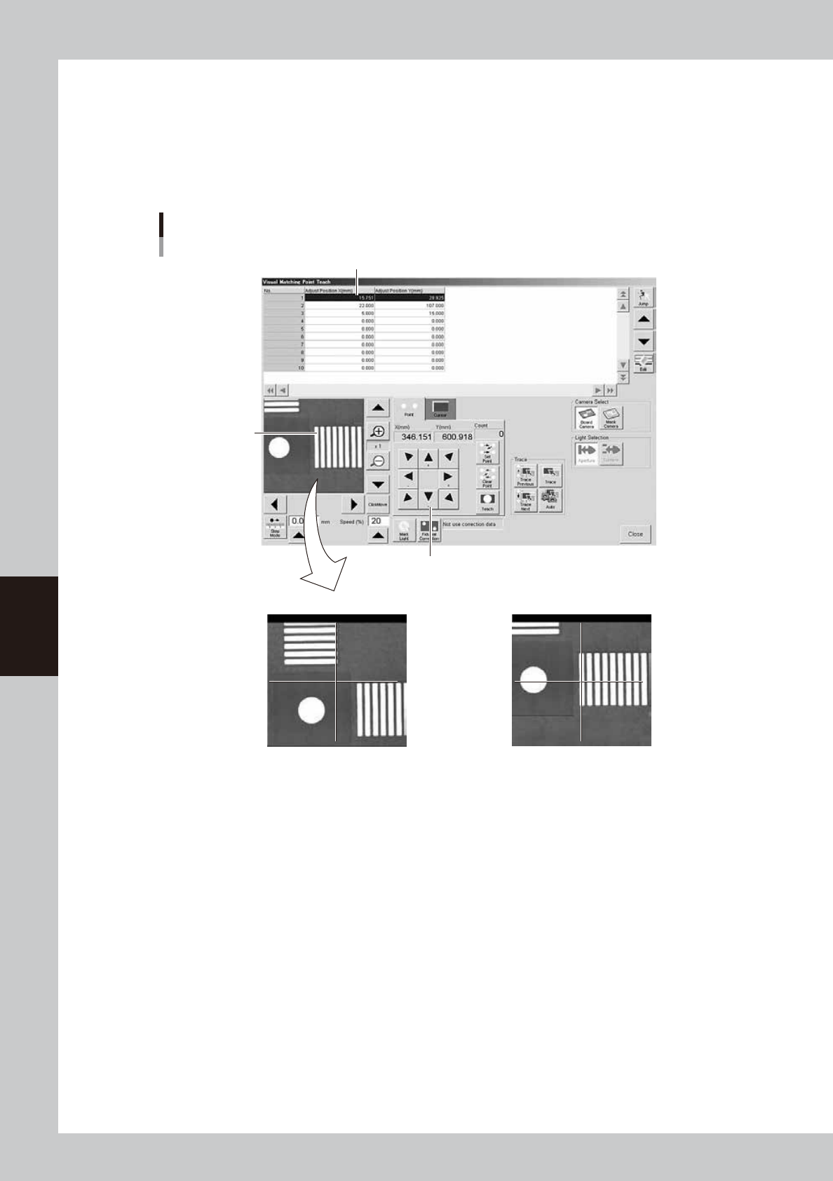
3
Teach the coordinates for graphic alignment.
1. Press the [Teach] button to open the teach window for graphic alignment.
2. Position the cursor on the first coordinates and press the [Trace] button.
3. Using the arrow keys, align the target coordinates (pad) with the center.
4. Press the [Teach] button to teach the coordinates.
Use the same method to teach the second point.
Teach window for graphic alignment
Arrow keys
Not OK OK
Pad to be aligned
Alignment coordinates
64539-N1-00
5-45
5
Creating and setting the data
4
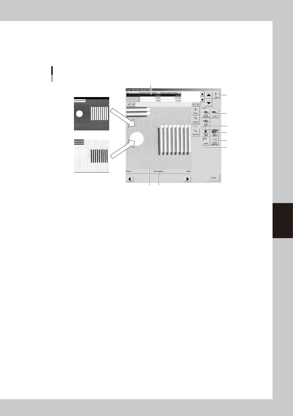
Check the graphic alignment.
1. After closing the teach window, press the [Setup] button and select the [Setup] tab.
2. Press the [Visual Matching] button to open the screen for graphic alignment check.
3. The vision monitor in this screen shows an overlapped image of the board and mask, so check the
board and mask alignment.
Screen for graphic alignment check
Board camera image
Mask camera image
1
4
5
6
9
8
7
2 3
64540-N1-00
1. Alignment coordinates
Select the coordinates where you want to check the board and mask alignment. These coordinates should first be set on
the [Print]-[Squeegee] tab screen. (See "5.1 Squeegee detail setting" in this chapter.)
2. Vision monitor
Shows an overlapped image of the board and mask.
The image can be enlarged from 1 to 16 times by pressing the enlarge [ + ] button, or reduced to 1/16 of the original
image by pressing the reduce [ - ] button. With the [Move] button depressed, you can move the image by dragging it with
the mouse.
3. Permeability
The transmittance of the board image and mask image can be adjusted with the slide bar or the arrow buttons.
4. [Teach] button
Opens the teach screen.
5. [Visual Matching] button
Opens the "Visual Matching" screen for making fine position alignments when needed. (See step 5.)
6. [Move Camera] button
Opens a screen for moving the vision camera unit.
7. [Move Table] button
Pressing this button moves the squeegee head to the inner end position and raises the board clamp table up to the back
surface of the mask. In this state, you can make a visual check of the board and mask alignment after pressing the
emergency stop button and then opening the upper door.
8. [Jump] button
Allows jumping to any desired row in the alignment coordinate list.
9. [Trace] button
Pressing the [Trace] button displays an image of the currently selected alignment coordinates. Pressing the [Trace
Previous] button displays an image of the alignment coordinates one row up from the currently selected coordinates.
Pressing the [Trace Next] button displays an image of the alignment coordinates one row down.