YCP10 Users_E.pdf - 第89页
3-13 3 Printing guide 3.2.5 T ransfer star t height n Function T his function sets the push-up height when releasing the board clamp as the height of the bottom surface mounting component, other protrusion part, or board…
3-12
3
Printing guide
3.2.4 X-axis movement during board transfer
n
Function
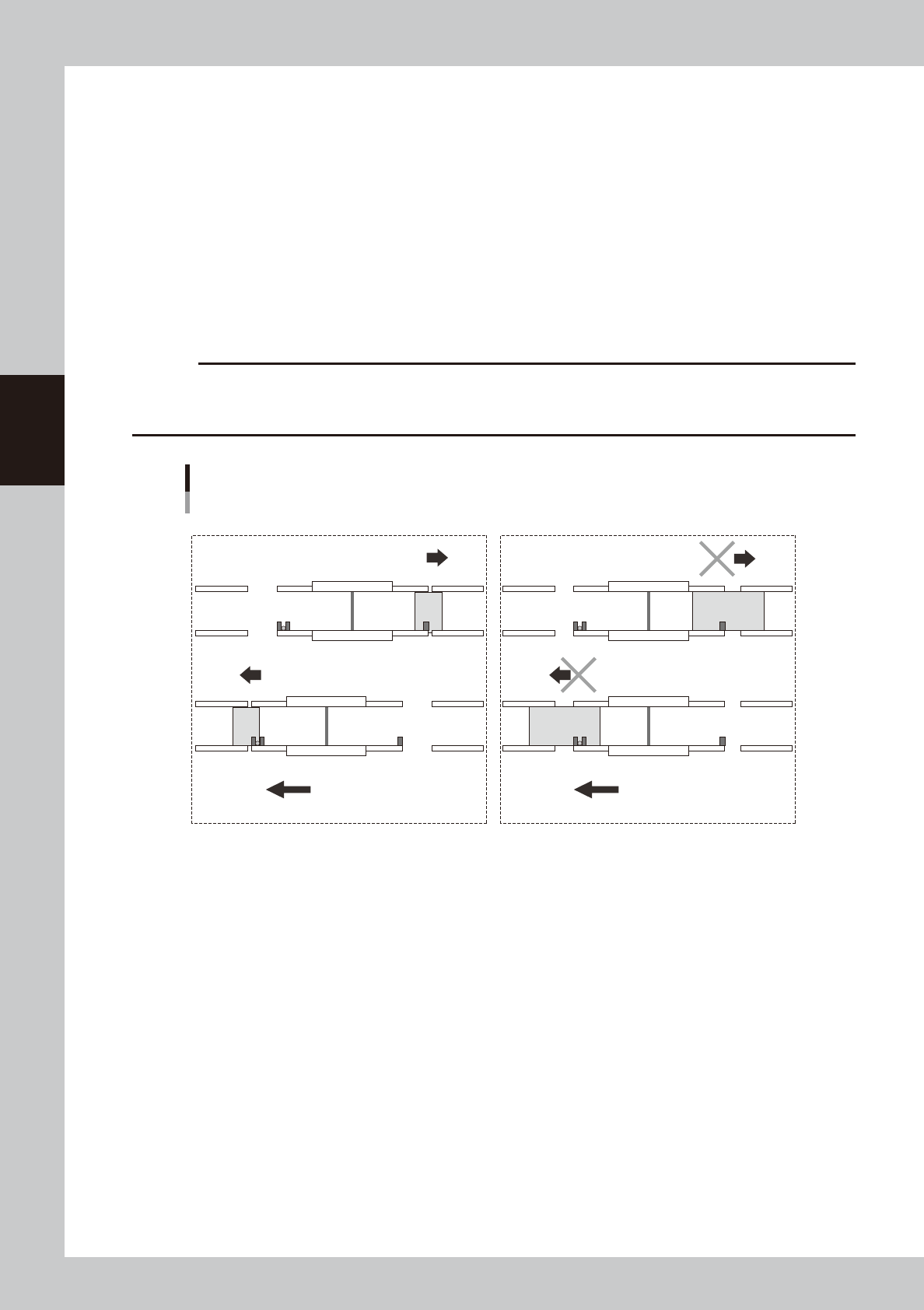
This function optimizes the X-axis coordinate of the print table when delivering the board between the upstream and
downstream machines so as to minimize the time loss associated with the movement.
n
Setting procedure
Set "z. X-Axis Move For Board Transfer" on the [Print]-[Board] tab screen.
Use: The X-axis (print table) is moved and transfers the board when delivering the board between the upstream and
downstream machines.
Not Use: The X-axis (print table) does not move to the soft limit when delivering the board between the upstream and
downstream machines.
c
CAUTION
This function is enabled only when the board size X is 100.0 mm or more.
When the board size X is less than 100.0 mm, this function performs the operation with "Not Use" setting regardless of
the setting.
X-axis movement during board transfer
■ Operation when selecting "Use". ■ Operation when selecting "Not Use".
Transfer direction (right → left) Transfer direction (right → left)
X-axis movement
Board
Upstream machineDownstream machine Upstream machineDownstream machine
Board
X-axis movement
X-axis movement
X-axis movement
63309-N1-00
3-13
3
Printing guide
3.2.5 Transfer start height
n
Function
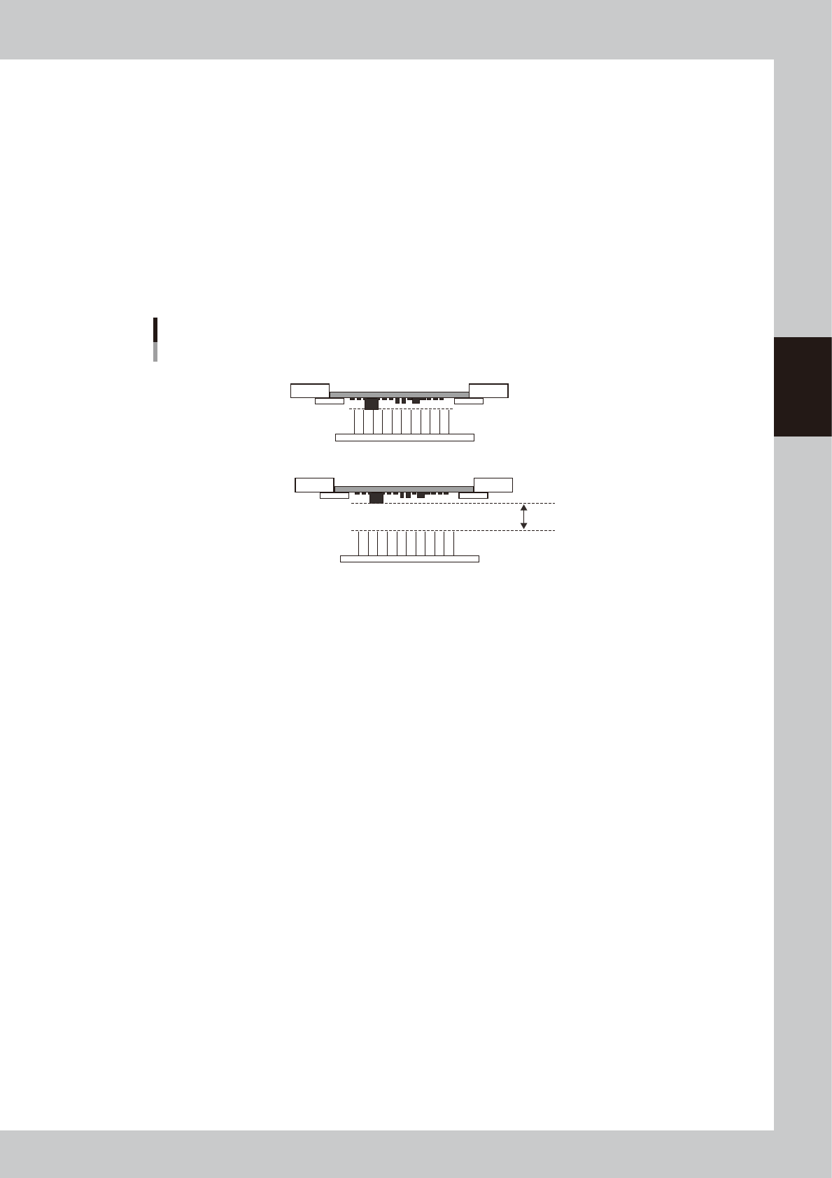
This function sets the push-up height when releasing the board clamp as the height of the bottom surface mounting
component, other protrusion part, or board warpage is set.
n
Setting procedure
Set "m. Trans Height" on the [Print]-[Board] tab screen.
Enter a numeric value ranging from 0 to 50 mm showing how many millimeters the transfer height is lowered from the
height of the bottom surface mounted component or board warpage.
When this parameter is set at "0 mm", the transfer height lowers to the maximum down height.
The initial value is "0 mm".
Transfer start height
Set this height.
Board is clamped.
Board clamp is released.
63310-N1-00
3-14
3
Printing guide
3.3 Board and mask mark recognition (Mark position)
n
Function
These parameters set coordinates of the fiducial mark positions of the board and mask. The camera moves to the mark
position to recognize the fiducial mark so as to align the board and mark positions.
n
Setting procedures
Enter accurate coordinates based on the CAD data of the board and mask.
3.4 Alignment offset
n
Function
Normally, the board and mask mark positions are set with the CAD data. Therefore, as each mark is recognized, the
board pattern is aligned with the mask apertures precisely. However, if any deviation, such as elongation of board
occurs, these offset values are used to correct this deviation.
n
Setting procedures
Offset values can be set in the X, Y, Z, and R directions.
To set offset values in the X, Y, and R directions, press the [Visual Matching] button on the [Basics] tab screen to set them.
n
NOTE
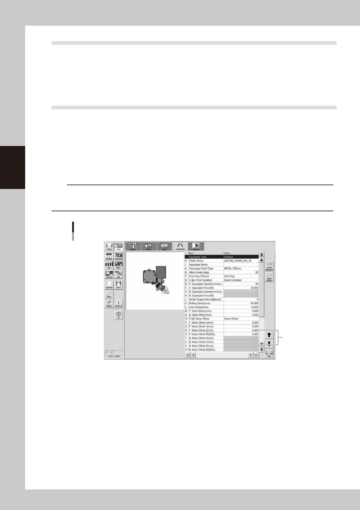
You cannot set the offset values in the Z direction with the graphic alignment. Check the contact status between the
mask and board during the rolling test. Enter appropriate values in the [Mask Offset Z] fields on the [Squeegee] tab
screen directly.
Alignment offset Z
Enter values
in these fields.
64305-N1-10