YCP10 Users_E.pdf - 第83页
3-7 3 Printing guide 3. Details of each parameter item T o continuously per form the production with excellent printing quality , it is absolutely required to properly set conditions for each solder paste printer as desc…
3-6
3
Printing guide
2.4 Printing and production conditions
Printing and production conditions
Step 1
Step 2
Step 3
64303-N1-10
1
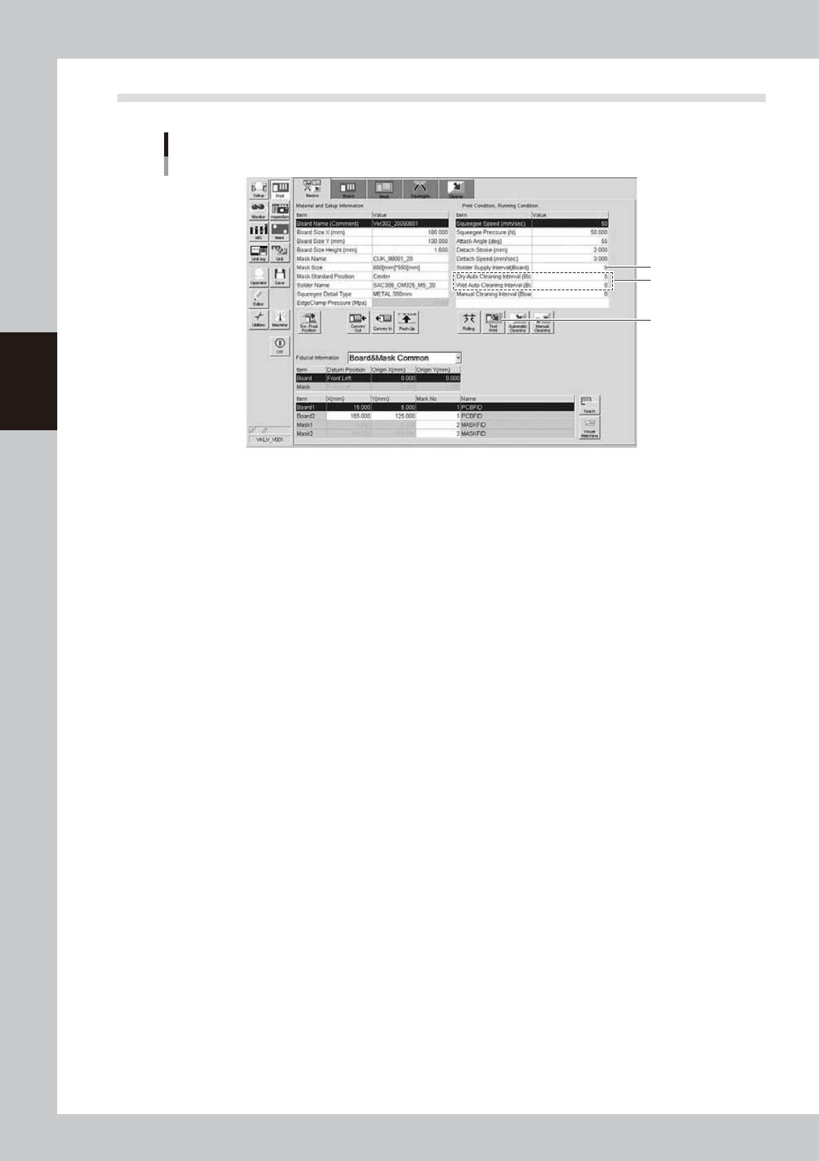
Start the test print.
1. Press the [Test Print] button. Follow the messages that appear on the operation screen to load a
board, perform the printing, and unload the board.
2. Visually check the printed board.
3. If any print trouble is found, change relevant conditions by referring to "4. Causes of troubles by
symptoms" in this chapter.
4. Start the test print again with the condition data you have changed.
2
Set cleaning conditions.
1. Enter a numeric value in the [Cleaning Interval] field. At this time, when the value is set at “0”, the
cleaning is not performed.
2. Start the cleaning with the cleaning speed and cleaning repeat set at their initial values. If you want
to change the value in the [Cleaning Speed] or [Cleaning Repeat] field, set the value on the
[Cleaner] tab screen.
Enter values as described above and start the production. If any print trouble caused by cleaning
occurs, change the values appropriately.
3
Set a solder supply interval.
Set how many boards are printed by one solder supply operation.
Normally, enter the number of boards that may consume 10 to 20% of the solder supply volume.
3-7
3
Printing guide
3. Details of each parameter item
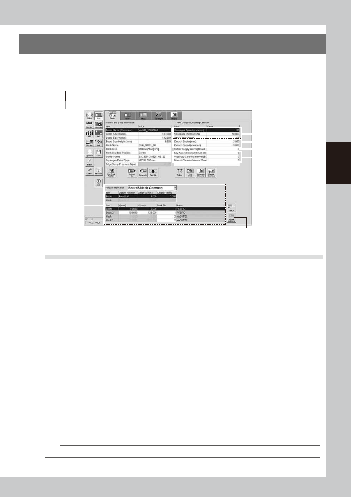
To continuously perform the production with excellent printing quality, it is absolutely required to properly set
conditions for each solder paste printer as described previously.
The following describes how the conditions for each operation affect the printing quality.
Each parameter item
3.3 Mark position 3.4 Alignment offset
3.5 Rolling
3.7 Detach pattern
3.8.1
Cleaning interval
3.6 Solder supply interval
64304-N1-10
3.1 Board clamp
3.1.1 Edge clamp pressure
n
Function
This parameter sets a level of the air pressure supplied to the cylinder which is used to catch a board and clamp it.
n
Setting range and initial value
This parameter can be set in a range of 0.001 to 0.225MPa.
The initial value is 0.225MPa.
n
Setting procedures
Adjust the edge clamp pressure with the regulator so that the board does not move or deform.
3.1.2 Backup jig
n
Function
This jig supports a board from the bottom when it is clamped.
n
Setting procedures
There are three kinds of backup jigs as described below.
• Matrix pin : Used with the push-up pins inserted into the matrix plate. (Printing of B-surface of double
sided mounted board, etc.)
• Flat surface backup : Used with the blocks (support jigs) placed on the matrix plate. (Mounted board with one
flat side)
• Vacuum gripper backup : Used for boards having a height of 0.5 mm or less. (This backup is set on the [Board] tab
screen.)
n
NOTE
Matrix pins and flat surface backup can be used together to support a board.
3-8
3
Printing guide
3.2 Board transfer
The YCP10 adapts a "servo transfer" that does not use the main stopper.
Unlike the transfer using the main stopper, since the positioning of the board stop position is performed by the
sensor response and servomotor RPM, the board stop position may vary depending on the transfer speed, board
material, surface treatment, shape, or weight.
In particular, when using bottom surface mounting boards, the board push-up may occur by the push-up
material during board clamp.
Therefore, functions to make the positioning of the board stop position stable are enhanced. Furthermore, in
addition to the functions to make the positioning stable, functions to make the transfer tact faster are also
provided. Make the settings appropriately according to the board.
c
CAUTION
Before starting the production, check the transfer sufficiently to make sure that any board push-up or drop does not
occur.
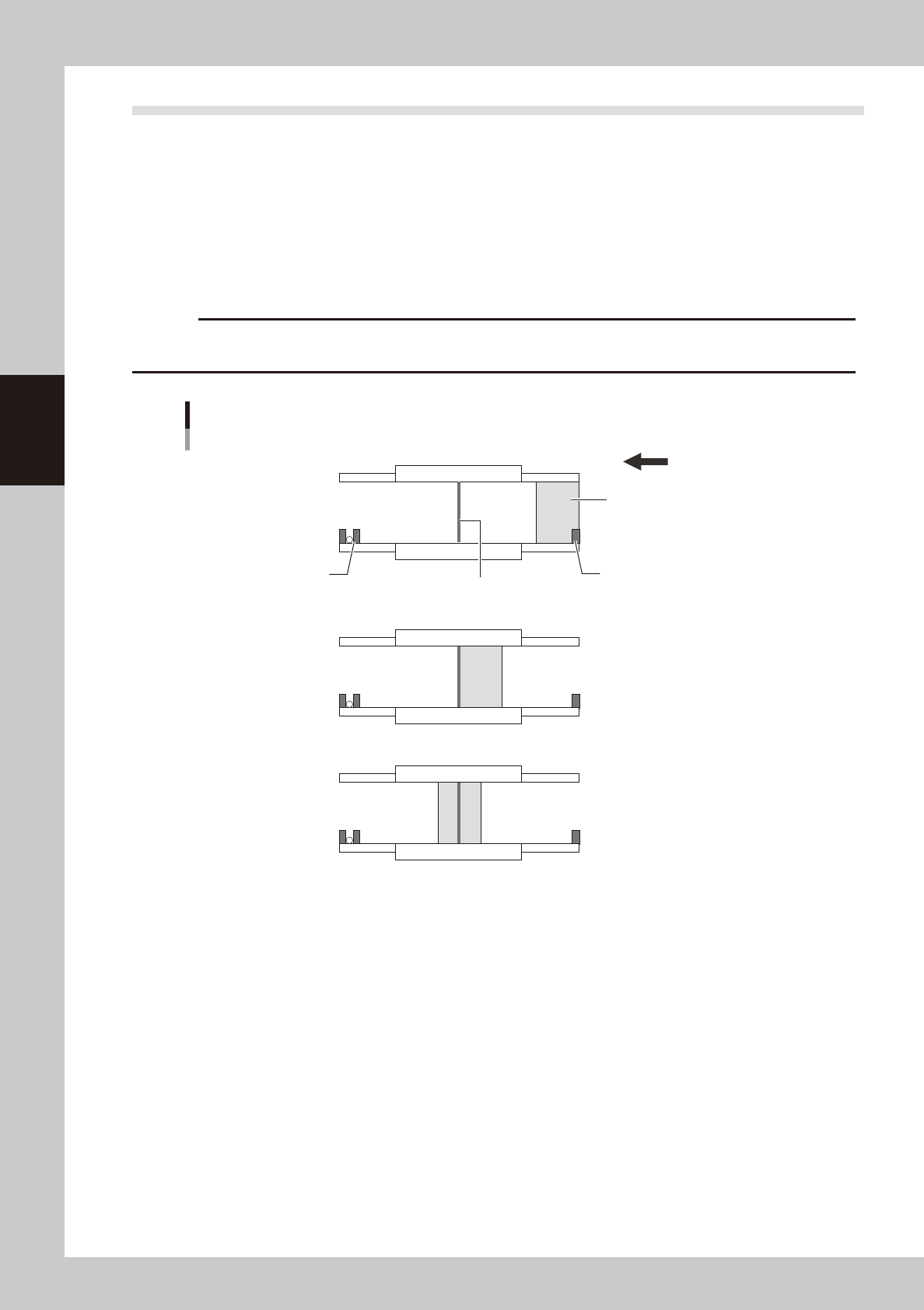
Board transfer using servo transfer
■ Transfer start
■ Board detection
■ Transfer completion
Exit sensor
Entrance sensor
Board
Printing position sensor
Transfer direction (right → left)
63307-N1-00
3.2.1 Transfer position check
n
Function
This function recognizes a desired mark by the board vision camera to correct the deviation amount of the transfer
position before board clamp.
This function increases the positioning accuracy of the board clamp.
n
Setting procedure
On the [Print]-[Board] tab screen, set "p. Carried Pos. Check" to "Enable" and set the values for related parameters.
(For details about how to set each parameter, see "3.1 Board marks and parameter setting" in Chapter 5.)