3OM-1003-005.pdf - 第117页
(C02_03) P-No. Shown are the step Nos. of the placement data (P). Set coordinates and angles for component placement in the lines of the step Nos. (P-Nos.). (C02_04) X [mm] and Y [mm] Set coordinates X and Y for componen…
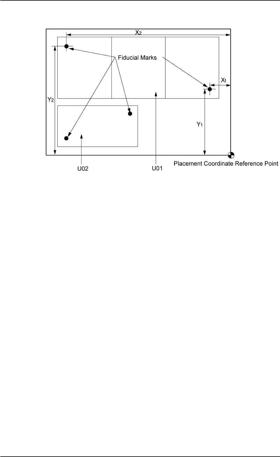
(2) "U-N" in "P.E.C. recognition mode image" Text Box
Fig. 3B95 Example of Two Units
• Set parameters in the "Recog Coord X1 [mm]", "Recog Coord Y1
[mm]", "Recog Coord X2 [mm]", "Recog Coord Y2 [mm]", "Fidu-
cial Mark FM1", and "Fiducial Mark FM2" text boxes for each unit.
• The recognition coordinates must be specified, regarding the
placement coordinate reference as an origin.
2.5 Placement Data
0305-001 2-47 AIL01EDTP
(C02_03) P-No.
Shown are the step Nos. of the placement data (P).
Set coordinates and angles for component placement in the lines of
the step Nos. (P-Nos.).
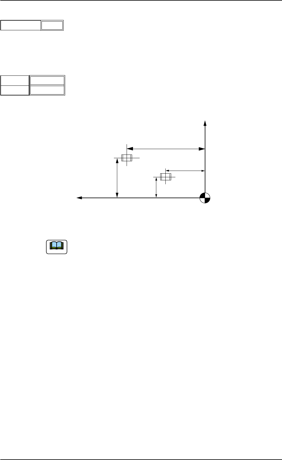
(C02_04) X [mm] and Y [mm]
Set coordinates X and Y for component placement.
The coordinates must be based on the placement coordinate refer-
ence point (N
0
).
Unit: mm
Fig. 3B98
(a) Do not set any coordinates for component placement in the last line
(last step No.).
Keep them as "000.000".
(b) To use the unit P.C.B. B.B.R. detection function (option), set the co-
ordinates of the bad mark to be put on in the "X [mm]" and "Y [mm]"
text boxes of the P-No. 1 step.
Refer to "3.5 Repetitive Patterns (Unit P.C.B. B.B.R. Function En-
abled) for concrete examples.
Y
X
Y
2
Y1
X1
X2
Placement Coordinate Reference (N0)
2.5 Placement Data
0305-001 2-48 AIL01EDTP
1
P-No.
Fig. 3B96
Fig. 3B97
X [mm]
Y
[mm]
010.000
010.000
Note
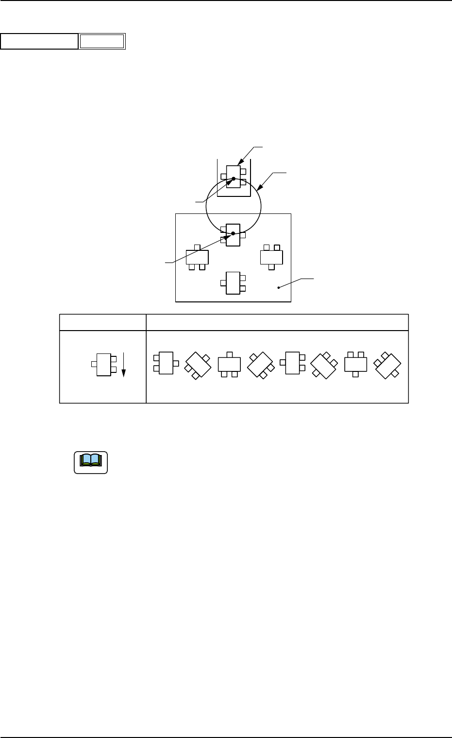
(C02_05) Z
= =
= =
= theta [deg]
Set angles for component placement.
Unit: degree
The placement angles must be determined according to the pack-
aged posture of components on the tape or the bulk feeder.
Example:
Fig. 3B100
Do not set any angle for component placement in the last line
(last P-No.).
Keep it as "+000.00".
Rotary Turret
90°
180°
270°
0°
Z
0° 45° 90° 135° 270°225°180°
315°
Packaged Posture
User Direction
of Feed
Packaged Posture of Component on
Tape Feeder
P.C.B.
Component Pick-Up Station
Component Placement Station
2.5 Placement Data
0305-001 2-49 AIL01EDTP
Fig. 3B99
+000.00
Z = theta [deg]
Note