3OM-1003-005.pdf - 第181页
(4) Press the [YES] button. The line (step) of the selected P-No. is trans- ferred to the step just above the specified line (step). Fig. 3B172 051 1-002 2-1 10 AIL01EDTP 4.4 "Placement Data" T ab
Transfer of P-No.
(1) Select the P-No. to be transferred with the touch screen or the pointing
device.
The selected line (P-No.) turns blue, indicating that it is selected.
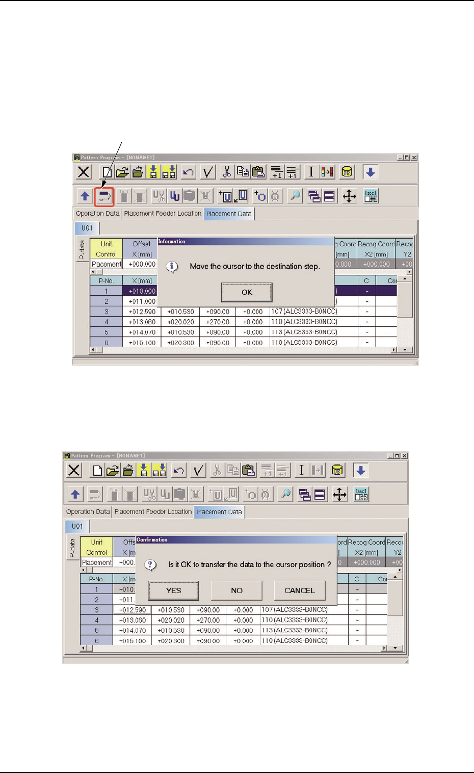
(2) Select the "Move the selected step data" icon.
Fig. 3B170
(3) Press the [OK] button and specify the destination step.
Fig. 3B171
4.4 "Placement Data" Tab
"Move the selected step data" Icon
051 1-002 2-109 AIL01EDTP
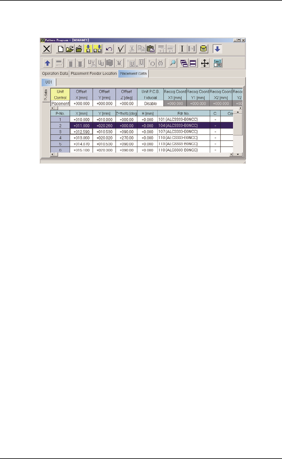
(4) Press the [YES] button. The line (step) of the selected P-No. is trans-
ferred to the step just above the specified line (step).
Fig. 3B172
051 1-002 2-1 10
AIL01EDTP
4.4 "Placement Data" Tab
4.4.3 "O-data" Tab
• Sheet Layout
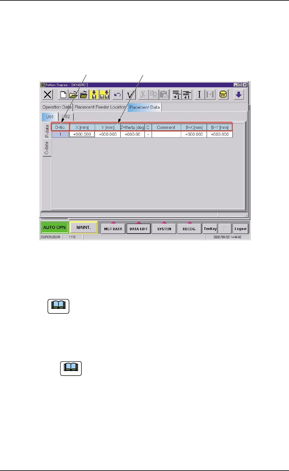
When the "O-data" tab is pressed in the "Placement Data" tab sheet,
the following tab sheet appears.
Fig. 3B173 "O-data" Tab Sheet
• Sheet Composition
Each parameter is displayed or can be entered.
Refer to "4.1.3 Basic Usage of Text Boxes" for the detailed in-
formation on how to enter each parameter.
*1 O-No.
Shown are the step Nos.
Follow the same steps as "• Operation Procedure" in "4.4.2
"P-data" Tab" on how to add or delete a step No. (O-No.).
*2 X [mm], Y [mm], Z=theta [deg], C, Comment, B-X [mm] (Option),
B-Y [mm] (Option)
*1 *2
4.4 "Placement Data" Tab
0305-001 2-111 AIL01EDTP
Note
Note