3OM-1003-005.pdf - 第297页
3.2.2 "Head" T ab The "Head" tab sheet is composed of "Head Origin", "Head Offset", and "Head Center Offset" tabs. • Sheet Layout When the "Head" tab is pressed…

0305-001 5-17 AIL01EDTP
*12 X/Y table chute width [mm]
This is the offset value indicating the difference between the chute
width of the X/Y table and the actually measured value.
(a) Measure the actual value at the P.C.B. outlet/input sec-
tions (fixed sections). Do not perform the measure-
ment at the roller position of the slide block.
(b) The actual value should be measured after the con-
veyor width is changed when the clearance data and
device offset are regarded as "0" (zero).
*13 Support pin up/down [mm]
This is the offset value indicating the difference between the P.C.B.
thickness and the length of the support pin (actually measured value).
*14 Unit P.C.B. B.B.R. (Option)
X [mm], Y[mm]
This is the offset data used to correct the positional deviation of the
unit P.C.B. B.B.R. detection sensor.
X [mm] : Positional Correction Data in Horizontal Direction
Y [mm] : Positional Correction Data in Vertical Direction
3.2 "Device Offset" Tab
Note
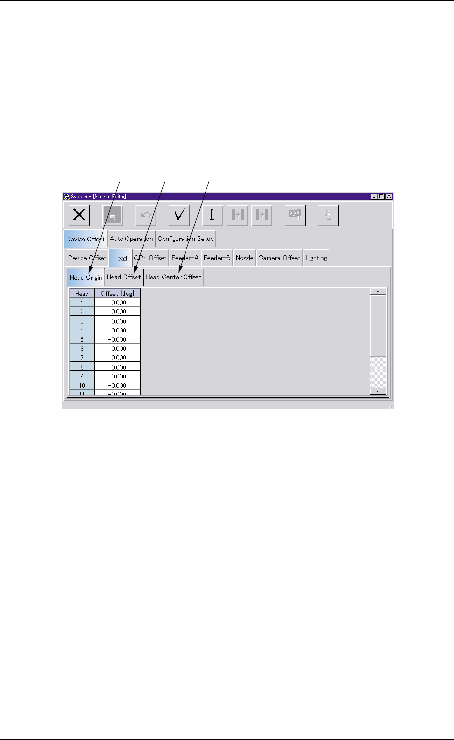
3.2.2 "Head" Tab
The "Head" tab sheet is composed of "Head Origin", "Head Offset", and
"Head Center Offset" tabs.
• Sheet Layout
When the "Head" tab is pressed in the "Device Offset" tab sheet, the
following tab sheet appears.
Fig. 3E19
• Sheet Composition
*1 [Head Origin] Tab
When selected, the "Head Origin" tab sheet appears.
*2 [Head Offset] Tab
When selected, the "Head Offset" tab sheet appears.
*3 [Head Center Offset] Tab
When selected, the "Head Center Offset" tab sheet appears.
0305-001 5-18
AIL01EDTP
*1
*2
*3
3.2 "Device Offset" Tab

(1) "Head Origin" Tab Sheet
• Sheet Layout
When the "Head Origin" tab is pressed in the "Head" tab sheet, the fol-
lowing tab sheet appears.
Fig. 3E20 "Head Origin" Tab Sheet
• Sheet Composition
*1 Head
The head Nos. are displayed.
0305-001 5-19
AIL01EDTP
*1
*2
3.2 "Device Offset" Tab