3OM-1003-005.pdf - 第300页
(2) "Head Offset" T ab • Sheet Layout When the "Head Offset" tab is pressed in the "Head" tab sheet, the following tab sheet appears. Fig. 3E22 "Head Offset" T ab Sheet • Sheet Com…
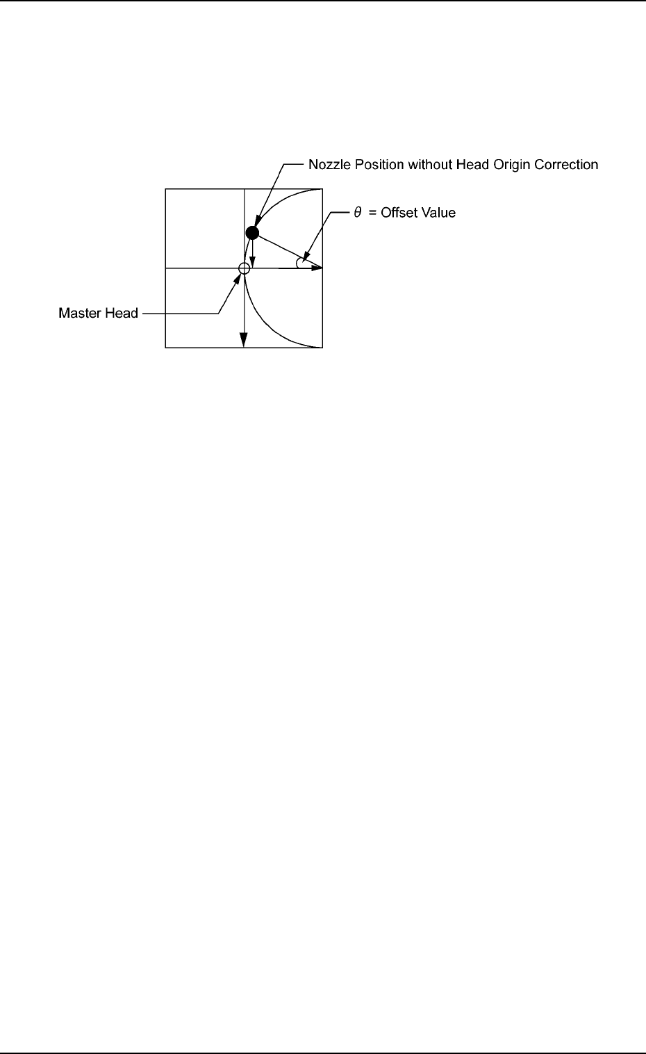
*2 Offset [deg]
The parameters are used to correct the variations in the origin posi-
tions of the nozzles on each head.
The difference between the master head and the reference value is
automatically calculated through teaching operation.
Fig. 3E21
0305-001 5-20
AIL01EDTP
3.2 "Device Offset" Tab
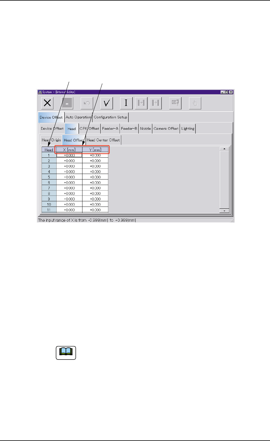
(2) "Head Offset" Tab
• Sheet Layout
When the "Head Offset" tab is pressed in the "Head" tab sheet, the
following tab sheet appears.
Fig. 3E22 "Head Offset" Tab Sheet
• Sheet Composition
*1 Head
The head Nos. are displayed.
*2 X [mm], Y [mm]
This is the offset data for positional adjustment based on the #1
head position and used when a head other than the #1 head is at-
tached.
(a) It is not necessary to enter any parameter for the #1
head because it is selected as the reference head.
Note: The entered parameters are reflected as offset
values.
Use this function to adjust the head positions after
checking how components are placed.
(b) These parameters are used to correct positional de-
viations between heads caused by each head up/down
guide.
0305-001 5-21
AIL01EDTP
3.2 "Device Offset" Tab
*1 *2
Note
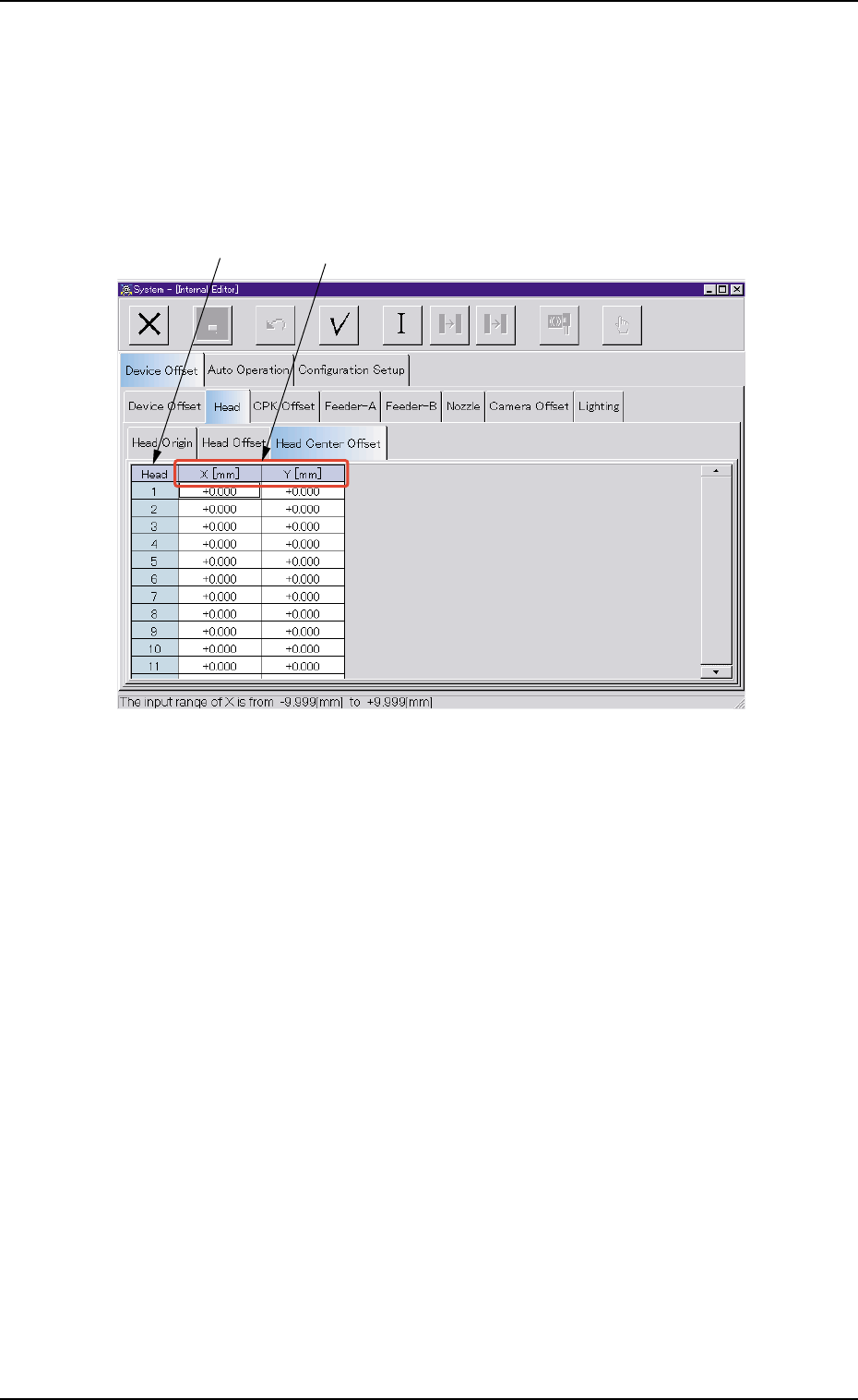
(3) "Head Center Offset" Tab
• Sheet Layout
When the "Head Center Offset" tab is pressed in the "Head" tab sheet,
the following tab sheet appears.
Fig. 3E23 "Head Center Offset" Tab Sheet
• Sheet Composition
*1 Head
The head Nos. are displayed.
*1 *2
3.2 "Device Offset" Tab
0305-001 5-22 AIL01EDTP