3OM-1003-005.pdf - 第304页
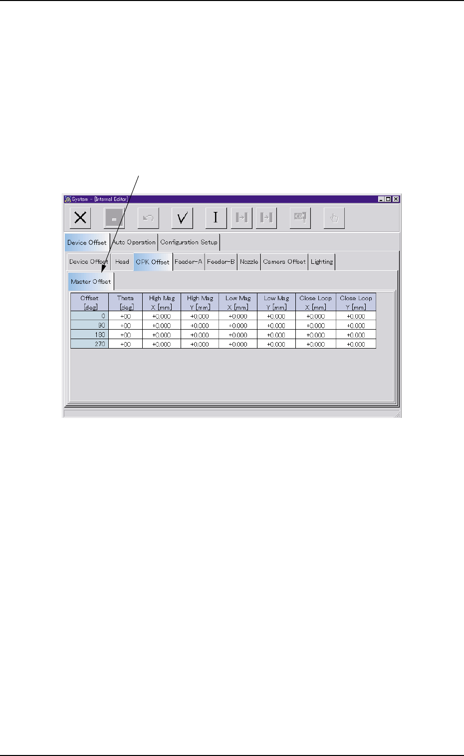
(1) "Master Offset" T ab • Sheet Layout When the "Master Offset" tab is pressed in the "CPK Offset" tab sheet, the following tab sheet appears. Fig. 3E26 "Master Offset" T ab Sheet…
3.2.3 "CPK Offset" Tab
The "CPK Offset" tab sheet is composed of "Master Offset" tab.
• Sheet Layout
When the "CPK Offset" tab is pressed in the "Device Offset" tab sheet,
the following tab sheet appears.
Fig. 3E25
• Sheet Composition
*1 "Master Offset" Tab
When selected, the "Master Offset" tab sheet appears.
0305-001 5-24
AIL01EDTP
3.2 "Device Offset" Tab
*1
(1) "Master Offset" Tab
• Sheet Layout
When the "Master Offset" tab is pressed in the "CPK Offset" tab sheet,
the following tab sheet appears.
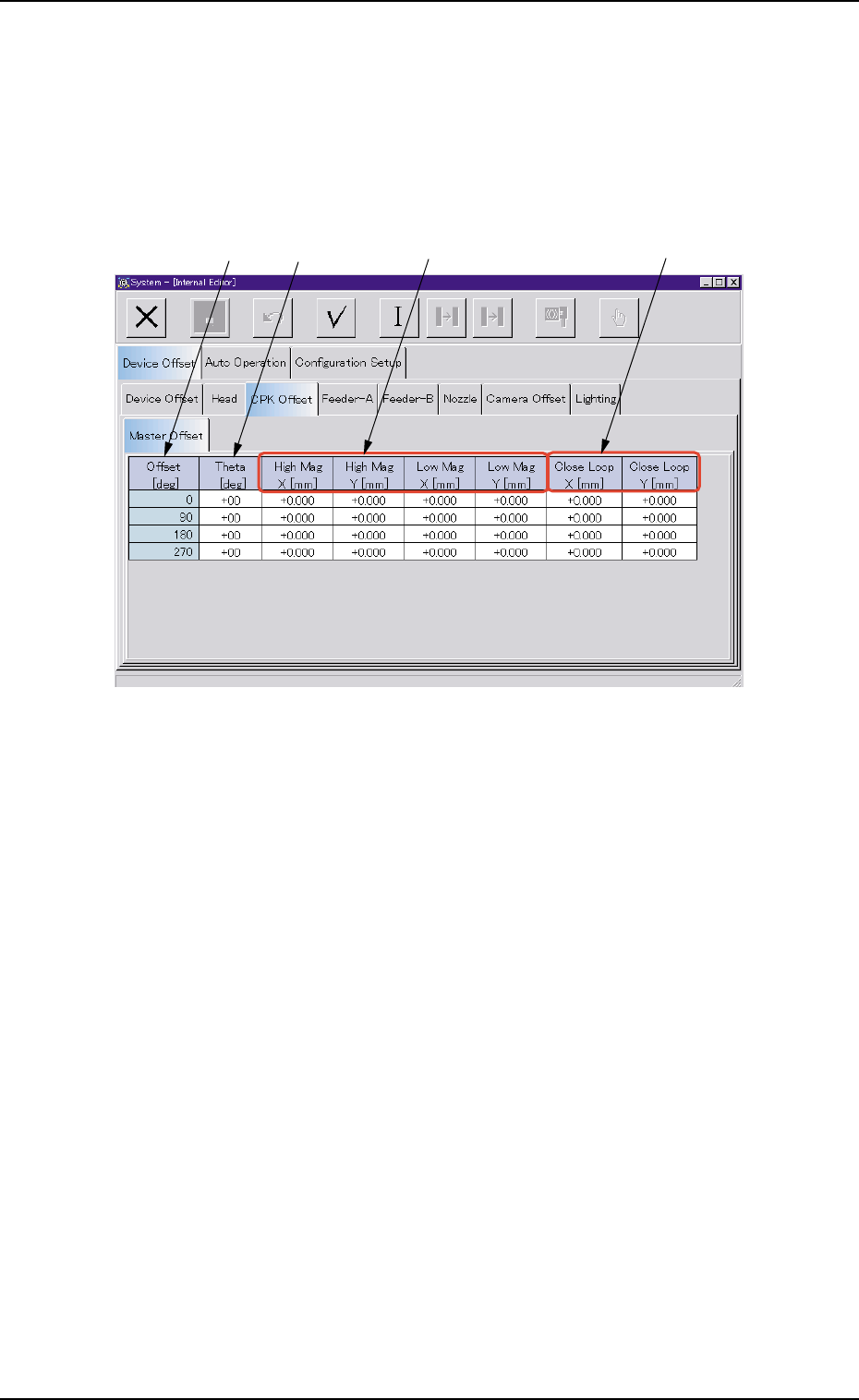
Fig. 3E26 "Master Offset" Tab Sheet
• Sheet Composition
*1 Offset [deg]
Displayed are the angles (0, 90, 180, and 270) specified in the place-
ment data.
*2 Theta [deg]
This is the offset data for angle difference between the X/Y table and
camera coordinate systems.
0305-001 5-25
AIL01EDTP
3.2 "Device Offset" Tab
*1 *2 *3 *4

*3 High Mag X [mm], High Mag Y [mm], Low Mag X [mm], Low Mag
Y [mm]
The travel of the X/Y table is corrected according to the angle (0°,
90°, 180°, or 270°, 4 directions) specified in the placement data
when components are placed.
(a) The data input range is "-0.15 to +0.15 mm"
(b) When parameters with "+" sign are entered for both "X
[mm]" and "Y [mm]", they are added to the parameters
in the "X" and "Y" directions of the pattern program data.
(c) Change each parameter every time deviated compo-
nent position (X and Y) is found as a result of compo-
nent placement based on each placement angle data.
*4 Close Loop X [mm], Close Loop Y [mm]
(Not Available)
0305-001 5-26
AIL01EDTP
3.2 "Device Offset" Tab
Note