3OM-1003-005.pdf - 第277页
(5) [D: comp. Recog.] Button Each text box shows the number of component recognition errors. (6) [E: comp. Thick] Button Each text box shows the number of errors in component thickness detected by the linear measure sens…
5.4 "Nozzle Bypass Rate" Tab
The corresponding tab sheet displays the pick-up rates (managed for
each individual nozzles) based on the nozzle bypass rates specified in
the auto operation setup data.
• Sheet Layout
When the "Nozzle Bypass Rate" tab is pressed in the "Bypass & Rate
Data" window, the following tab sheet appears inside the window.
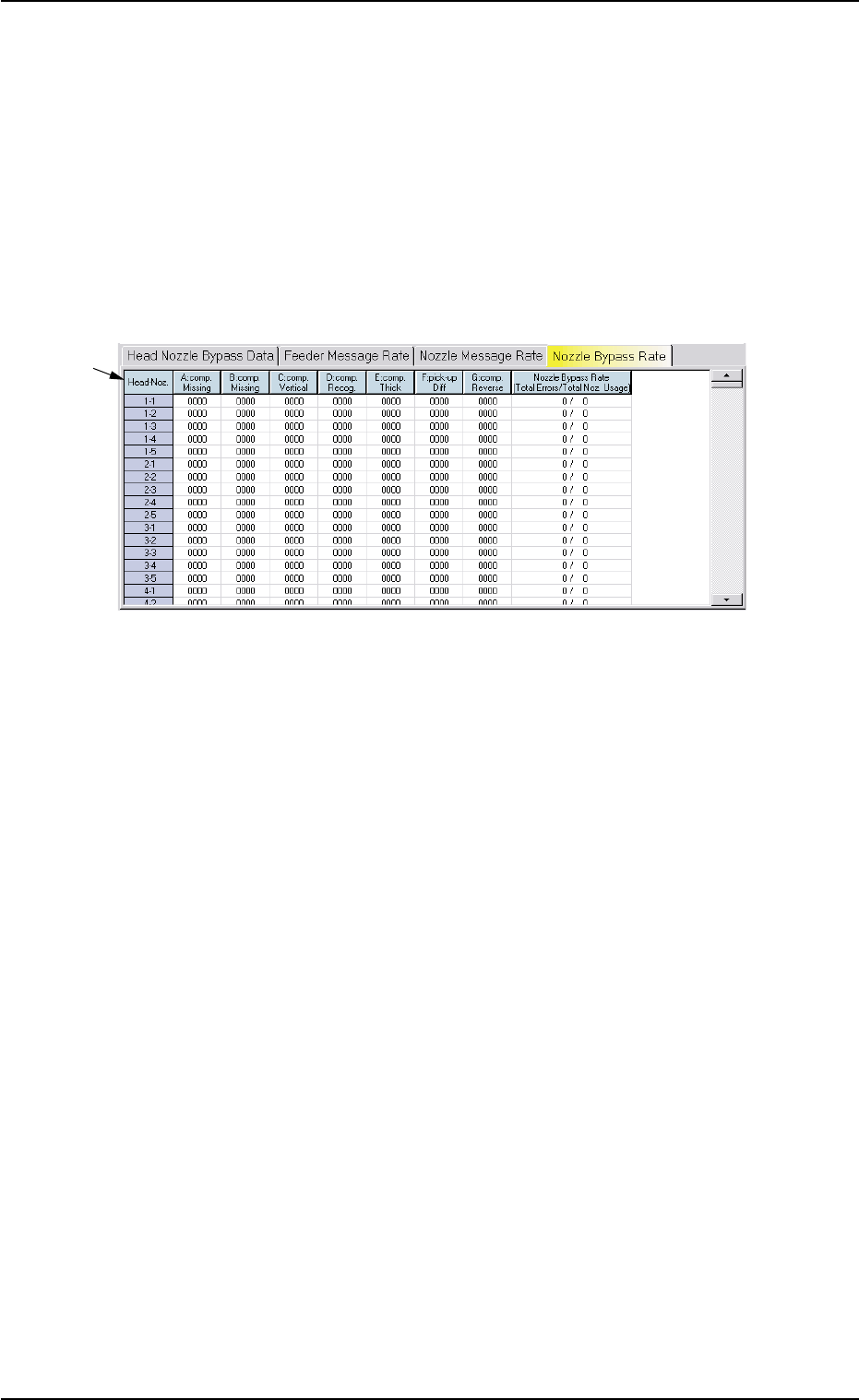
Fig. 3D24 "Nozzle Bypass Rate" Tab Sheet
• Sheet Composition
*1 Items
The following items are displayed.
(1) [Head-Noz.] Button
Shown are the nozzle Nos. on each head No.
(2) [A: comp. Missing] Button
Each text box shows the number of missing component errors de-
tected by the linear measure detection sensor.
(3) [B: comp. Missing] Button
Each text box shows the number of missing component errors de-
tected through recognition operation.
(4) [C: comp. Vertical] Button
Each text box shows the number of vertical component errors de-
tected by the linear measure sensor for each individual nozzles.
*1
5.4 "Nozzle Bypass Rate" Tab
0305-001 4-51 AIL01EDTP

(5) [D: comp. Recog.] Button
Each text box shows the number of component recognition errors.
(6) [E: comp. Thick] Button
Each text box shows the number of errors in component thickness
detected by the linear measure sensor for each individual nozzles.
(7) [F: pick-up Diff] Button
Each text box shows the number of pick-up difference errors de-
tected through recognition operation for each individual nozzles.
(8) [G: Comp. Reverse] Button
Each text box shows the number of reversed component errors
detected through recognition operation for each individual nozzles.
(9) [Nozzle Bypass Rate (Total Errors/Total Noz. Usage)] Button
Each text box shows the rate of pick-up errors (the number of pick-
up errors per number of picks) for each individual nozzles.
5.4 "Nozzle Bypass Rate" Tab
0305-001 4-52 AIL01EDTP

Section 5
System Setting
0305-001 5-A AIL01EDTP
This section describes the functions and operations in each
window (window which opens after a menu button ([SYS DATA],
[NOZ DATA], or [MACH SETUP] button) is selected from the
"SYSTEM" menu).