3OM-1003-005.pdf - 第142页
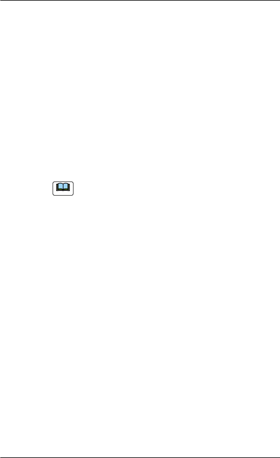
(2) Creation of Placement Data (P-data) T able 3B34 P-No. X [mm] Y [mm] Z = theta [deg] H [mm] Fdr . No. V C Comment 1 X 1 Y 1 Z 1 +0.000 X X X 0 0 - C1 2 X 2 Y 2 Z 2 +0.000 X X X 0 0 - C2 3 +000.000 +000.000 +000.00 +0.…
3.6 Repetitive Patterns (Block Sorting Enabled)
Follow the same procedure as described in "3.4 Repetitive Patterns
(Unit P.C.B. B.B.R. Enabled)" except for "Placement Data (P-data)".
(1) Information on Pattern Program Creation
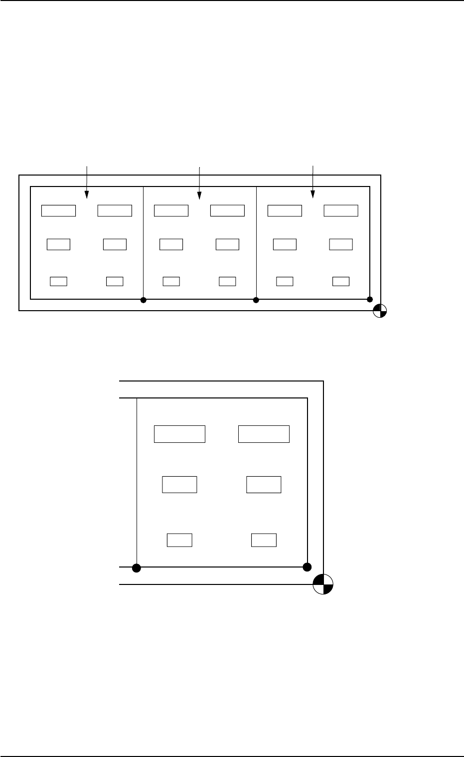
• Example of Patterns
Fig. 3B132 General View
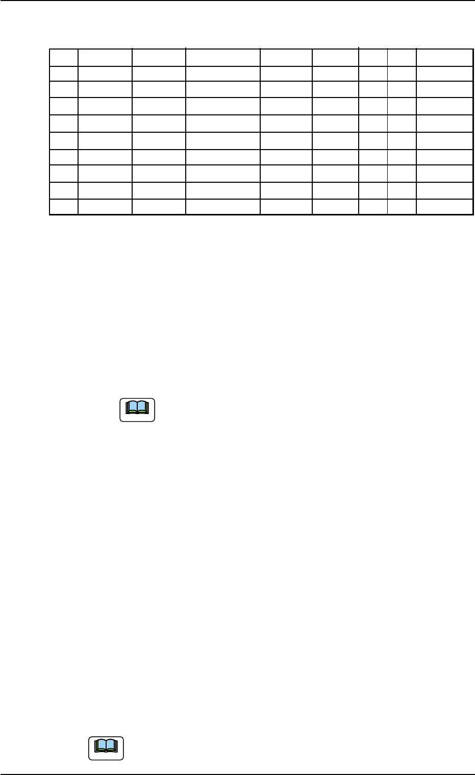
Fig. 3B133 Pattern 1 (Magnified View)
• X/Y Table Speed for Components
(Component Library Data)
C1 and C2: Full Speed
C3 and C4: 20%Decr
C5 and C6: 50%Decr
0305-001 2-72
AIL01EDTP
Placement Coordinate
Reference Point
Pattern 1
Pattern 2
Pattern 3
Placement Coordinate
Reference Point
C6
(X
6
, Y
6
)
(X
4
, Y
4
)
(X
2
, Y
2
)
(X
1
, Y
1
)
(X
3
, Y
3
)
(X
5
, Y
5
)
C4
C2
C3
C1
C5
3.6 Repetitive Patterns (Block Sorting Enabled)
(2) Creation of Placement Data (P-data)
Table 3B34
P-No. X [mm] Y [mm] Z = theta [deg] H [mm] Fdr. No. V C Comment
1 X
1
Y
1
Z
1
+0.000 XXX 00 - C1
2
X
2
Y
2
Z
2
+0.000 XXX 00 - C2
3 +000.000 +000.000 +000.00 +0.000 000 00 2
4 X
3
Y
3
Z
3
+0.000 XXX 00 - C3
5
X
4
Y
4
Z
4
+0.000 XXX 00 - C4
6 +000.000 +000.000 +000.00 +0.000 000 00 5
7
X
5
Y
5
Z
5
+0.000 XXX 00 - C5
8
X
6
Y
6
Z
6
+0.000 XXX 00 - C6
9 +000.000 +000.000 +000.00 +0.000 000 00 P
Procedure
(2-1) Classify the components into some pairs of groups that indi-
vidually require the same speeds of the X/Y table movement.
Allocate a pair groups of components that require the least
deceleration rate to the smallest "P-No." steps.
In this example, the parameters related to C1 and C2 are set
in the "P-No. 1" and "P-No. 2" steps.
(2-2) Set "2" in the "C" text box of the "P-No. 3" step and "0" (zero)
for the other data.
This step is handled as a delimiter of speed groups.
(a) The machine does not place any components for
the step where a delimiter of speed groups is speci-
fied.
(b) Control Command "2" does not mean that it is used
to control the speed of the X/Y table movement.
Any of the control commands (0 to 9) can be used
as a delimiter.
In this example, "2" is used to indicate that the com-
ponents in the "P-No. 4" step and the subsequent
ones require the 20% deceleration rate.
(2-3) Follow the same procedure to create each step as described
below.
• Set C3 and C4 in the "P-No. 4" and "P-No. 5" steps.
• Set "5" in the "C" text box of the "P-No. 6" step and "0" (zero)
for the other data.
• Set C5 and C6 in the "P-No. 7" and "P-No. 8" steps.
(2-4) Create the last step in the same way as a normal program. Be
sure to set "P" as a control command in the "C" text box.
Note: Actual component placement will be made in almost
the reverse sequence as explained below.
Up to 20 speed groups can be created in one pattern pro-
gram.
0305-001 2-73
AIL01EDTP
3.6 Repetitive Patterns (Block Sorting Enabled)
Note
Note
Order of Component Placement
The machine starts the placement operation with the components
that require less deceleration rate (deceleration of X/Y table move-
ment) as follows.
Pattern 1 (C1 Æ C2) Æ Pattern 2 (C1 Æ C2) Æ Pattern 3 (C1 Æ C2) Æ
Pattern 3 (C3 Æ C4) Æ Pattern 2 (C3 Æ C4) Æ Pattern 1 (C3 Æ C4) Æ
Pattern 1 (C5 Æ C6) Æ Pattern 2 (C5 Æ C6) Æ Pattern 3 (C5 Æ C6) Æ
Placement Data (O-data)
Follow the normal procedure to create this data.
Placement-Speed-Related Component Library Data
The following component library data also gives some effect to the
placement speed. (For your reference)
Speed Data: Pick-Up [sec], Rotary turret [sec], Placement [sec]
Feeder carriage, Recognition time [sec]
Refer to "COMPONENT LIBRARY (TCM-X Series)" for de-
tails of each speed data. (Another Instruction Manual)
0305-001 2-74
AIL01EDTP
3.6 Repetitive Patterns (Block Sorting Enabled)
Note