3OM-1003-005.pdf - 第90页
(A01_13) Feeder No. offset Set an offset value as an offset of "Fdr No." in the placement feeder location. The placement feeder location data is shifted as much as the speci- fied value and the machine performs…
(A01_11) Feeder standby position
Set a "Fdr No." (feeder slot No.) as a feeder standby position.
000 : This function is disabled.
Entry of "Fdr No." : After a piece of P.C.B. is finished, the feeder
carriage returns to the specified feeder slot
No. (Fdr No. = Pick-Up Position).
Data Input Range
TCM-X110J
101 to 159, 201 to 259
TCM-X300S
101 to 170, 201 to 270
Any feeder slot No. (Fdr No.) which does not exist in the placement feeder
location data cannot be specified.
(A01_12) Alternate mode
Select one of the following options to determine whether or not the
alternate function should be used.
Disable : The alternate function is disabled.
Alternate Carriage : The unit alternate function is enabled.
Alternate Pallet : The pallet alternate function is enabled.
(a) The feeder alternate function can be specified in the placement feeder
location data.
(b) In TCM-X110J and TCM-X300S, the alternate pallet mode has al-
most the same functions as the alternate carriage mode.
051 1-002 2-20
AIL01EDTP
2.3 Operation Data
000
Feeder standby position
Fig. 3B27
Alternate mode
Fig. 3B28
Disable
Note
Note
(A01_13) Feeder No. offset
Set an offset value as an offset of "Fdr No." in the placement feeder
location.
The placement feeder location data is shifted as much as the speci-
fied value and the machine performs the pick-up operation.
Data Setting
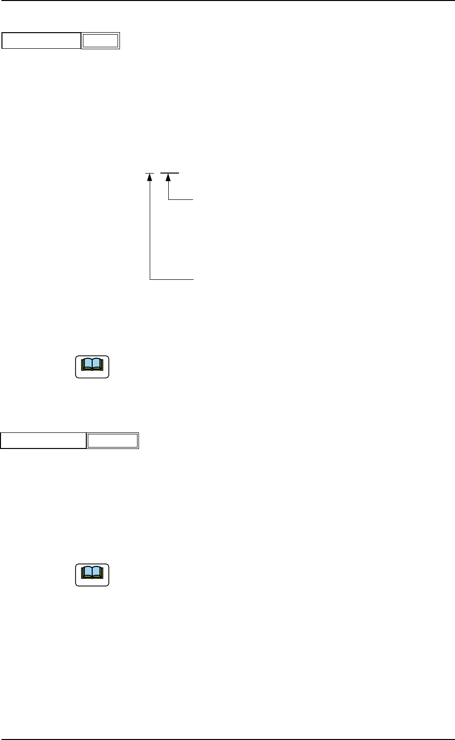
±{{{
These two digits show the offset in increments of a
feeder location.
Data Input Range
TCM-X110J : 00 to 59
TCM-X300S: 00 to 70
This digit shows the carriage No. to be shifted.
Data Input Range: 0 to 2
Fig. 3B30
(a) It is recommended that a value with a "+" (plus) sign should be en-
tered.
(b) Set "+000" not to use any offset.
(A01_14) X/Y table accel des
Select one of the following options to determine acceleration of the X/
Y table movement for component placement.
Full Speed 10%Decr 20%Decr 30%Decr
40%Decr 50%Decr 60%Decr 70%Decr
80%Decr 90%Decr
(a) In normal cases, select "Full Speed".
(b) When there are some previously-placed components, the transfer
speed can be decreased in advance to avoid component deviations
that may be caused by the X/Y table movement.
051 1-002 2-21 AIL01EDTP
2.3 Operation Data
+000
Feeder No. offset
Fig. 3B29
Full SpeedX/Y table accel des
Fig. 3B31
Note
Note
(A01_15) C1 accel des, C2 accel des
Select one of the following options to determine acceleration of each
feeder carriage movement for component picks.
Full Speed 10%Decr 20%Decr 30%Decr
40%Decr 50%Decr 60%Decr 70%Decr
80%Decr 90%Decr
(A01_16) Recovery regulation
U-N
When placement data is created to cope with the Un-specified multi-
model repetitive pattern function, the recovery regulation must be en-
abled.
Refer to "2.1 Types of P.C.B.’s and Required Data" for de-
tailed information on how to specify "Un".
Disable : The recovery regulation function is disabled.
The normal automatic recovery function is activated.
Enable : The recovery regulation function is enabled.
When the automatic recovery function is activated, a pat-
tern with the smallest "Un" No. is recovered first and the
subsequent patterns are recovered in the ascending or-
der.
As long as all components in the pattern (smaller Un No.)
are not recovered, no components are placed on the sub-
sequent Un No. (Unit).
051 1-002 2-22
AIL01EDTP
2.3 Operation Data
Fig. 3B33
U
-N
Block
Disable
Disable
C1 accel des
Fig. 3B32
Full Speed
C2 accel des
Full Speed
Note