3OM-1003-005.pdf - 第169页
*2 Fdr No. Shown under this key are the feeder Nos. (a) Refer to " • Operation Procedure" (described later) for the detailed information on how to add or delete feeder Nos. (Fdr Nos.). (b) When the background c…
4.3 "Placement Feeder Location" Tab
4.3.1 "Feeder Carriage" Tabs
• Sheet Layout
When the "Feeder Carriage #1" tab is pressed in the "Placement
Feeder Location" tab sheet, the following tab sheet appears.
Follow the same procedure to make the "Feeder Carriage #2"
visible.
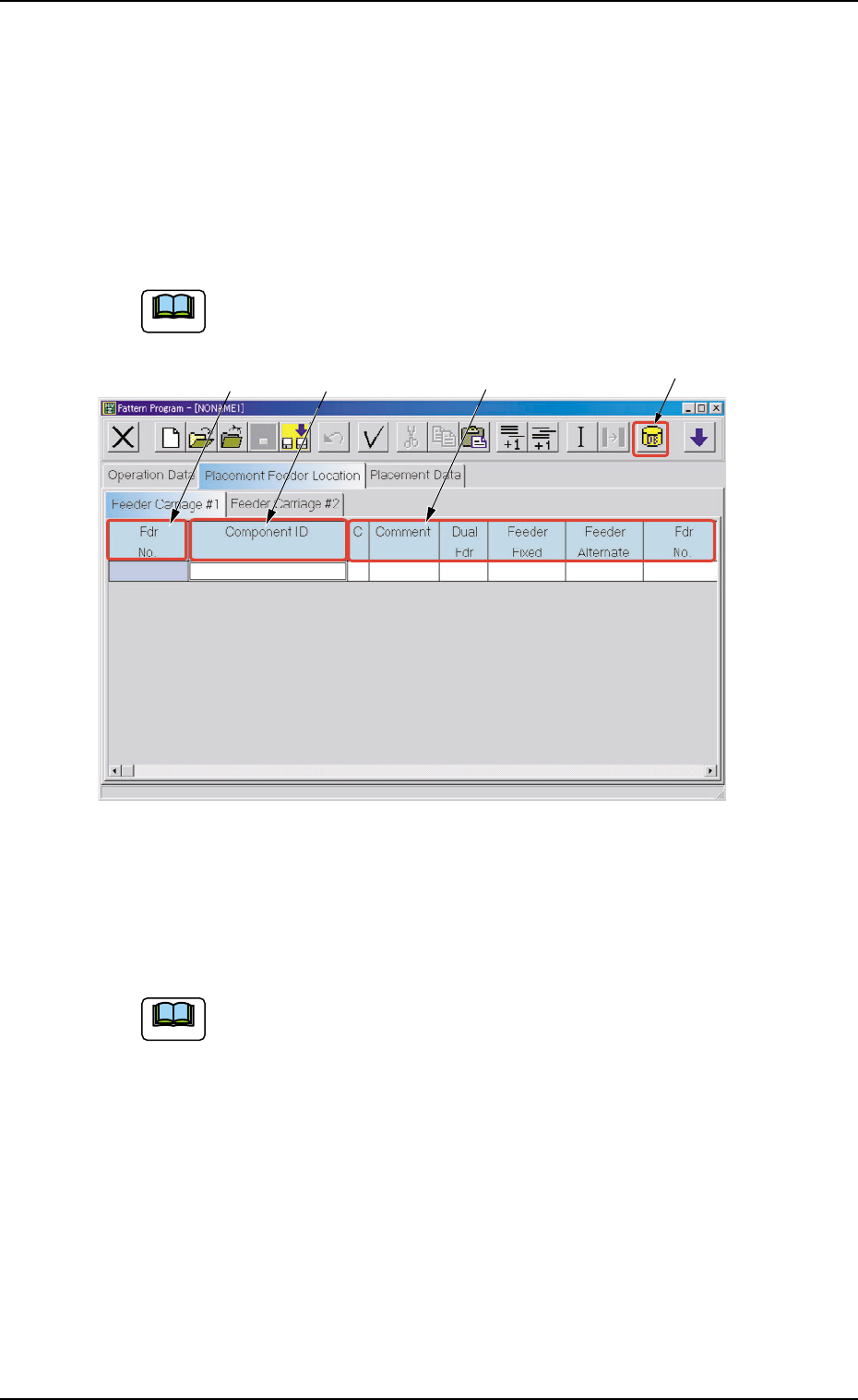
Fig. 3B159 "Feeder Carriage #1" Tab Sheet
• Sheet Composition
Each parameter is displayed or can be entered.
Refer to "4.1.3 Basic Usage of Text Boxes" for the detailed in-
formation on how to enter parameters.
*1 [Component ID List] Icon
When this icon is pressed, the "Component ID List" window opens.
This window enables you to select a component ID from the com-
ponent library and allocate it to an arbitrary feeder (Fdr. No.)
Refer to "4.3.2 "Component ID List" Window" for details.
4.3 "Placement Feeder Location" Tab
*1
*2 *3
*4
051 1-002 2-97 AIL01EDTP
Note
Note
*2 Fdr No.
Shown under this key are the feeder Nos.
(a) Refer to "• Operation Procedure" (described later) for
the detailed information on how to add or delete feeder
Nos. (Fdr Nos.).
(b) When the background color is black, it indicates that
the feeders have exceeded the maximum installable
number.
Avoid this by deleting a feeder No. (Fdr. No.).
*3 Component ID
Displayed are the currently allocated component IDs.
Refer to "4.3.2 "Component ID List" Window" for how to
enter or delete a component ID.
*4 C, Comment, Dual Fdr, Feeder Fixed, Feeder Alternate, Fdr
No.
Enter a parameter in each text box.
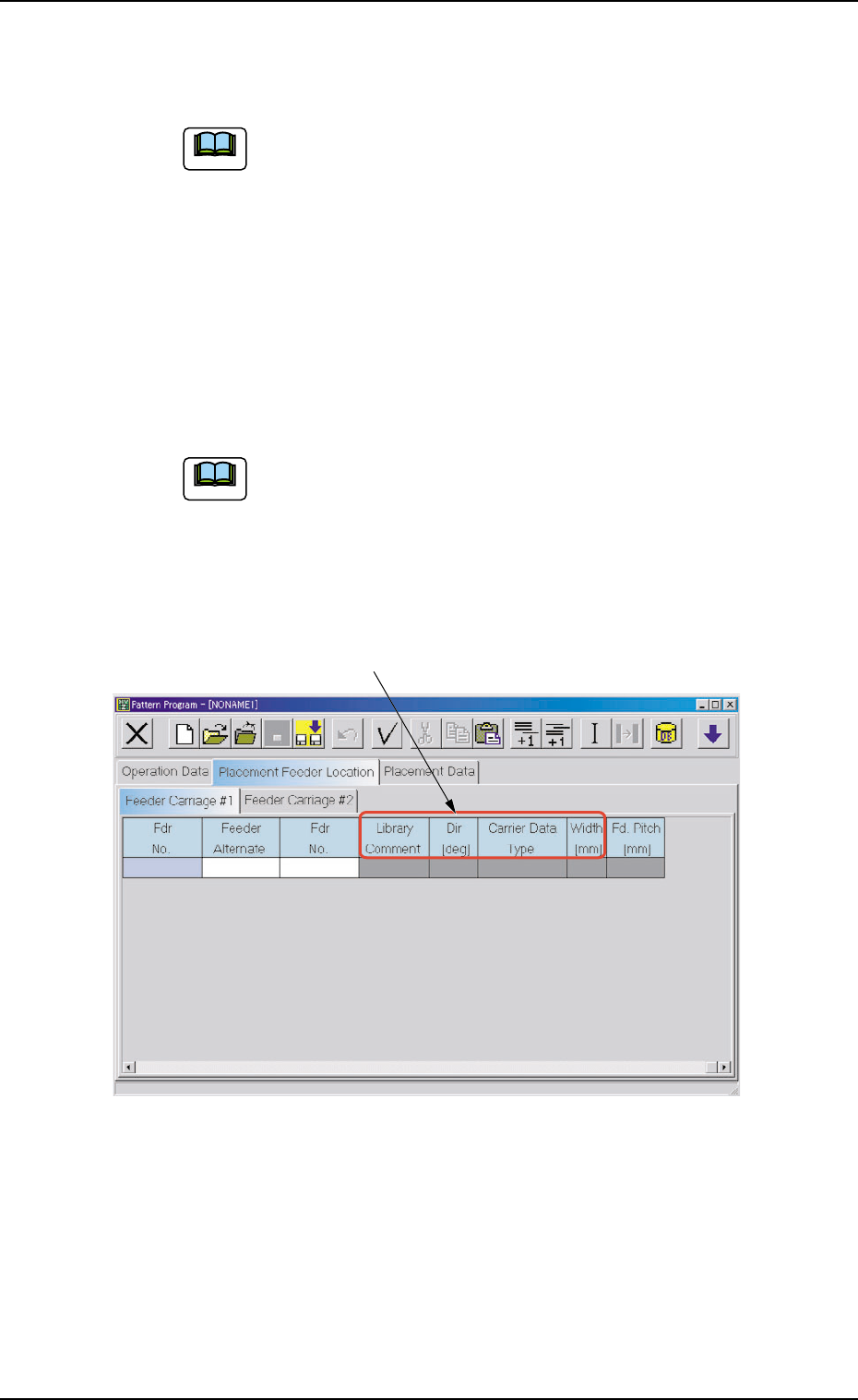
Fig. 3B160 "Feeder Carriage #1" Tab Sheet
*5 Library Comment, Dir [deg], Carrier Data Type, and Width [mm]
Displayed are the parameters specified in the component library.
*5
4.3 "Placement Feeder Location" Tab
051 1-002 2-98 AIL01EDTP
Note
Note
• Operation Procedure
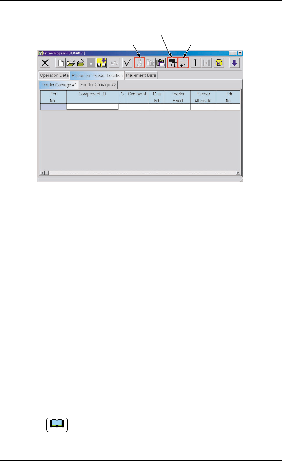
Fig. 3B161 Menu for Editing
Addition of "Fdr No."
(1) Select [Add Line] icon on the menu.
A new "Fdr No." is added to the last line (last Fdr No.).
Insertion of "Fdr No."
(1) Select the position where a Fdr. No. should be inserted with the
touch screen or the pointing device.
The selected line (Fdr. No.) turns blue, indicating that it is selected.
(2) Select [Insert Line] icon on the menu.
A new line (Fdr No.) is inserted at the selected line and the subse-
quent lines (Fdr Nos.) are shifted down.
Deletion of "Fdr No."
(1) Select the Fdr. No. to be deleted with the touch screen or the point-
ing device.
The selected line (Fdr. No.) turns blue, indicating that it is selected.
(2) Select "Delete" on the menu.
The selected line (Fdr No.) is deleted and the subsequent lines (Fdr
Nos.) are shifted up.
Do not set any parameters for the feeder carriages that are not
used.
Otherwise, a data error occurs. If parameters are set, be sure
to delete them.
[Add Line] Icon
[Cut] Icon
[Insert Line] Icon
4.3 "Placement Feeder Location" Tab
051 1-002 2-99 AIL01EDTP
Note