3OM-1003-005.pdf - 第348页
*1 1 P .C.B. output buffer position Set "Outlet" or "Middle" as the P .C.B. buf fer position for P .C.B. transfer actions. Fig. 3E52 and Fig. 3E53 show that the P .C.B. flow direc- tion is "From …
Stop timer (Buffer #1) [sec]
Set the delay time (the period of time during which the sensor at the
buffer 1 position of the output conveyor detects a P.C.B. and the
conveyor stops) in the text box.
Stop timer (Buffer #2) [sec]
Set the delay time (the period of time during which the sensor at the
buffer 2 position of the output conveyor detects a P.C.B. and the
conveyor stops) in the text box.
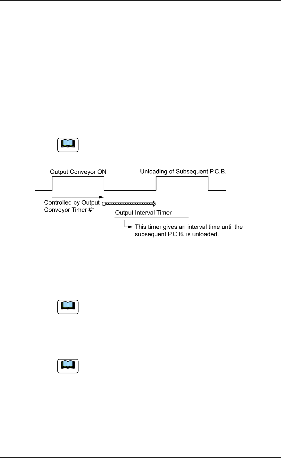
*8 Output interval timer [sec]
When "Interval" is set in the "Output mode" text box, set the time as
interval time for P.C.B. unloading actions.
The data input range is "0 to 99 seconds".
Fig. 3E51
*9 Buffer conveyor count [pcs]
Set the number of P.C.B. buffers on the input conveyor in this text
box.
"1" or "2" can be set in the text box.
*10 # of Buffereds P.C.B.’s to be discharged [pcs]
Set the number of P.C.B.’s that can be held in reserve ready for
production on the output conveyor.
Set "1" or "2" in the text box.
0305-001 5-60
AIL01EDTP
3.3 "Auto Operation" Tab
Note
Note
Note
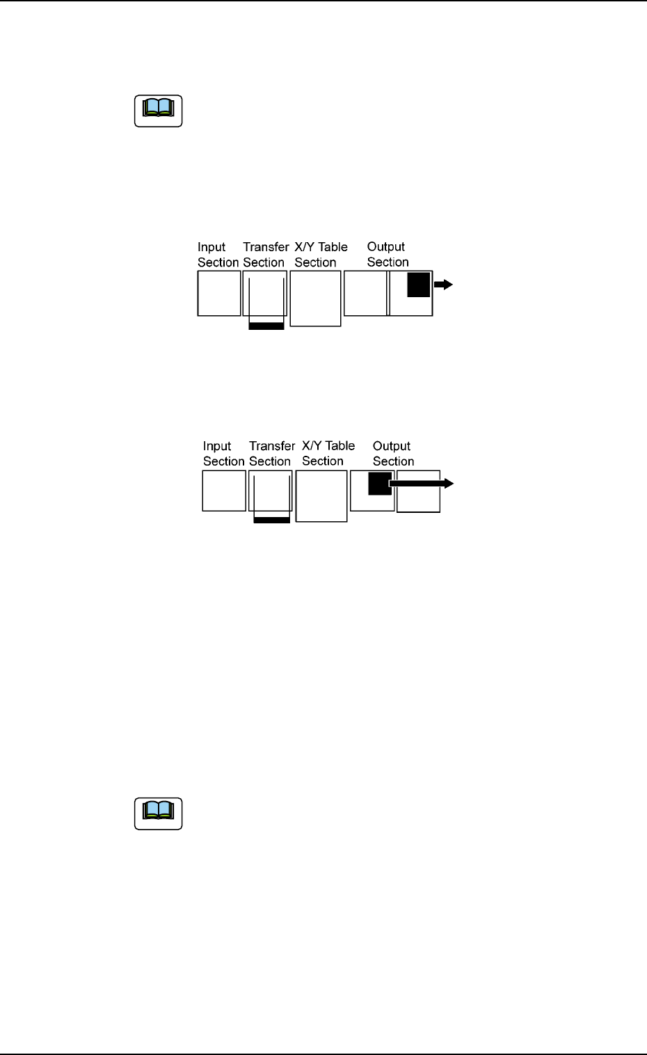
*11 P.C.B. output buffer position
Set "Outlet" or "Middle" as the P.C.B. buffer position for P.C.B. transfer
actions.
Fig. 3E52 and Fig. 3E53 show that the P.C.B. flow direc-
tion is "From Left to Right".
When the P.C.B. flow direction is "From Right to Left", the
reverse actions take place, compared with the figures.
Actions taken when "Outlet" is selected
Fig. 3E52
Action taken when "Middle" is selected
Fig. 3E53
*12 X/Y conveyor reverse stroke [mm]
Set the reverse stroke of the chute (X/Y) conveyor required when
the P.C.B. is transferred.
When the P.C.B. is fed over to the chute in the transfer operation,
the transfer claw might be kept away from the P.C.B.
The P.C.B. positioning will be completed normally by rotating the
chute (X/Y) conveyor in the reverse direction as much as the speci-
fied value to make the P.C.B. completely in contact with the transfer
claw.
Default (Value at Shipment): 5.0 mm
*13 P.C.B. clamp timer [sec]
Set the time of the P.C.B. clamp timer in the text box.
0305-001 5-61
AIL01EDTP
3.3 "Auto Operation" Tab
Note
Note

0305-001 5-62 AIL01EDTP
3.3 "Auto Operation" Tab
*14 Pass mode select
One of the following options can be selected as a way to pass a
P.C.B.
Conveyor : The conveyor is activated to pass a P.C.B.
Transfer claw : The conveyor and the P.C.B. transfer claw are ac-
tivated to pass a P.C.B.
*15 Output Conveyor P.C.B. Out
Set "Disable" or "Enable" in the text box to determine whether or not
a disengaged P.C.B. should be detected in the output conveyor sec-
tion.
*16 Furnace Signal Check
Set "Disable" or "Enable" in the text box to determine whether or not
the furnace signal check function should be used.
When "SMEMA" is set in the "Input mode" or the "Output
mode" text box, this function does not work.
*17 P.C.B. exist signal check
It must be determined whether or not the P.C.B. exist signal should
be checked.
No Check : The P.C.B. exist signal is not checked.
Input & Output : The P.C.B. exist signals from the input/output ma-
chines are checked.
Input : Only the P.C.B. exist signal from the input ma-
chine is checked.
Output : Only the P.C.B. exist signal from the output ma-
chine is checked.
(a) When a parameter other than "No Check" is set in the
"P.C.B. exist signal check" text box, the P.C.B.’s on the
conveyors of the input and output machines are de-
tected and the automatic setup actions, etc., are re-
stricted.
(b) When "SMEMA" is set in the "Input mode" or the "Out-
put mode" text box, this function does not work.
*18 Transfer conveyor reverse speed
When a P.C.B. is transferred, the rotation of the conveyor is re-
versed to bring the P.C.B. close to the transfer claw. The speed of
the reverse rotation can be specified in this text box.
Select one of the following options.
Full Speed, 10%Decr, 20%Decr, 30%Decr, 40%Decr,
50%Decr, 60%Decr, 70%Decr, 80%Decr, 90%Decr
Note
Note