3OM-1003-005.pdf - 第307页
0305-001 5-28 AIL01EDTP • Sheet Layout When the "Feeder Carriage #1" tab is pressed in the "Feeder-A" tab sheet, the following tab sheet appears. (a) Follow the same procedure for the "Feeder-B&q…

0305-001 5-27 AIL01EDTP
3.2.4 "Feeder-A" and "Feeder-B" Tabs
• "Feeder-A"
This is the offset data used to correct variation in each feeder slot No.
(Fdr. No.) of the feeder carriages.
The parameters measured at shipment of the machine are en-
tered.
Do not change the parameters unless necessary.
• "Feeder-B"
This is the offset data used to correct variation in each feeder slot No.
(Fdr. No.) of the feeder carriages.
X [mm], Y [mm]
When the [Enable] buttons are selected for both "(X) Dir." and "(Y)
Dir." in the "Auto Fdr. Axis Set" group box (Operation Sequence:
"[OPN. MODE] Button on Submenu Bar" Æ "Opn. Mode" Tab
Sheet"), component recognition processing is performed during
automatic operation to track the positional relation between the
nozzle and component centers. After that, the parameters (X and
Y) are automatically updated for better pickup posture (pickup on
the component center).
In normal cases, it is not necessary to enter any parameter.
L [mm]
These parameters are not updated automatically but the entered
ones are reflected.
3.2 "Device Offset" Tab
Note
0305-001 5-28 AIL01EDTP
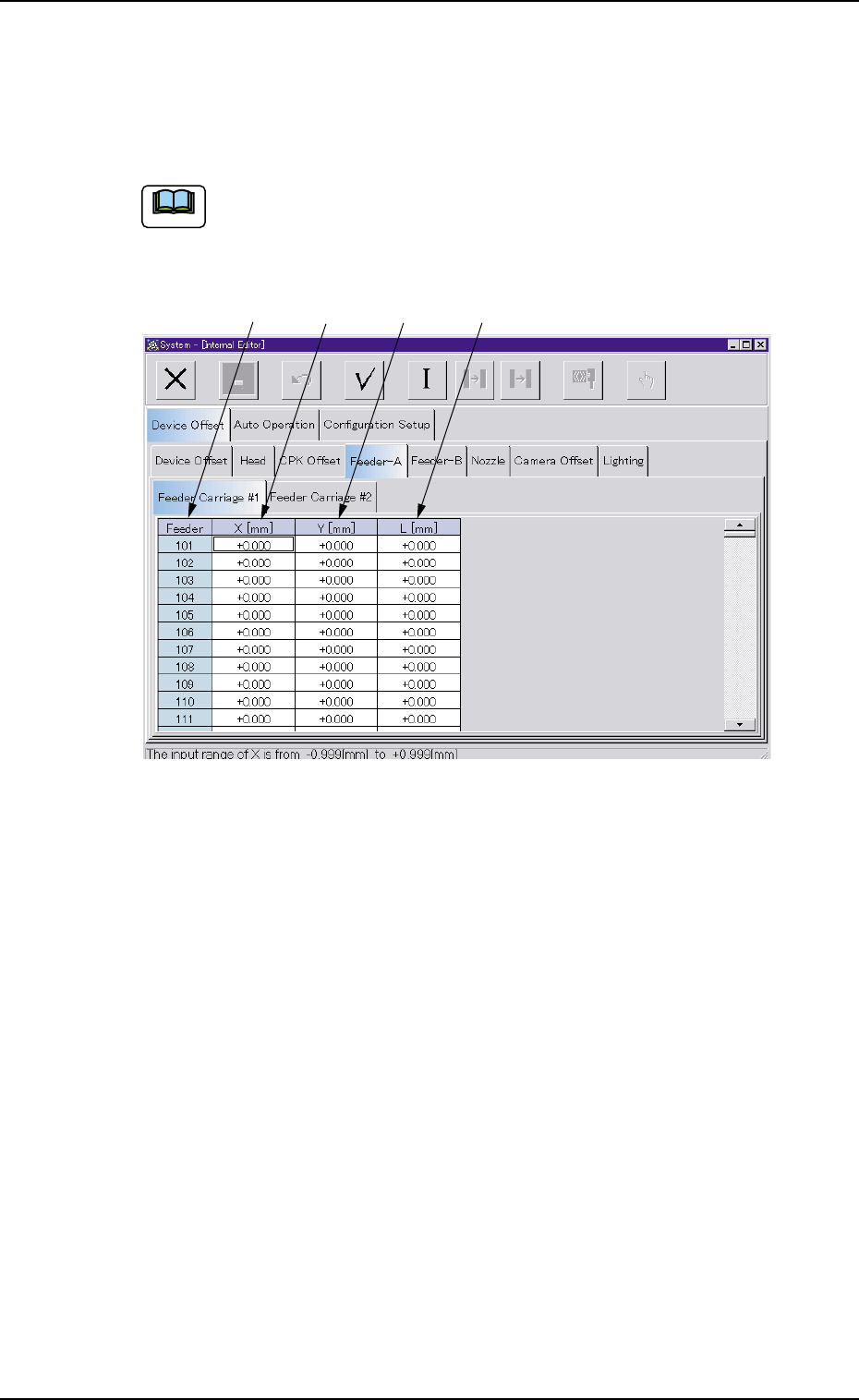
• Sheet Layout
When the "Feeder Carriage #1" tab is pressed in the "Feeder-A" tab
sheet, the following tab sheet appears.
(a) Follow the same procedure for the "Feeder-B" tab sheet.
(b) Follow the same procedure for the "Feeder Carriage #2"
tab sheet.
Fig. 3E27 "Feeder Carriage" Tab Sheet
• Sheet Composition
*1 Feeder
The feeder Nos. (Fdr. Nos.) are displayed.
*2 X [mm]
Each text box shows an offset value of the X direction.
*3 Y [mm]
Each text box shows an offset value of the Y direction.
*4 L [mm]
Each text box shows an offset value of the L direction.
3.2 "Device Offset" Tab
*1
*2
*3 *4
Note
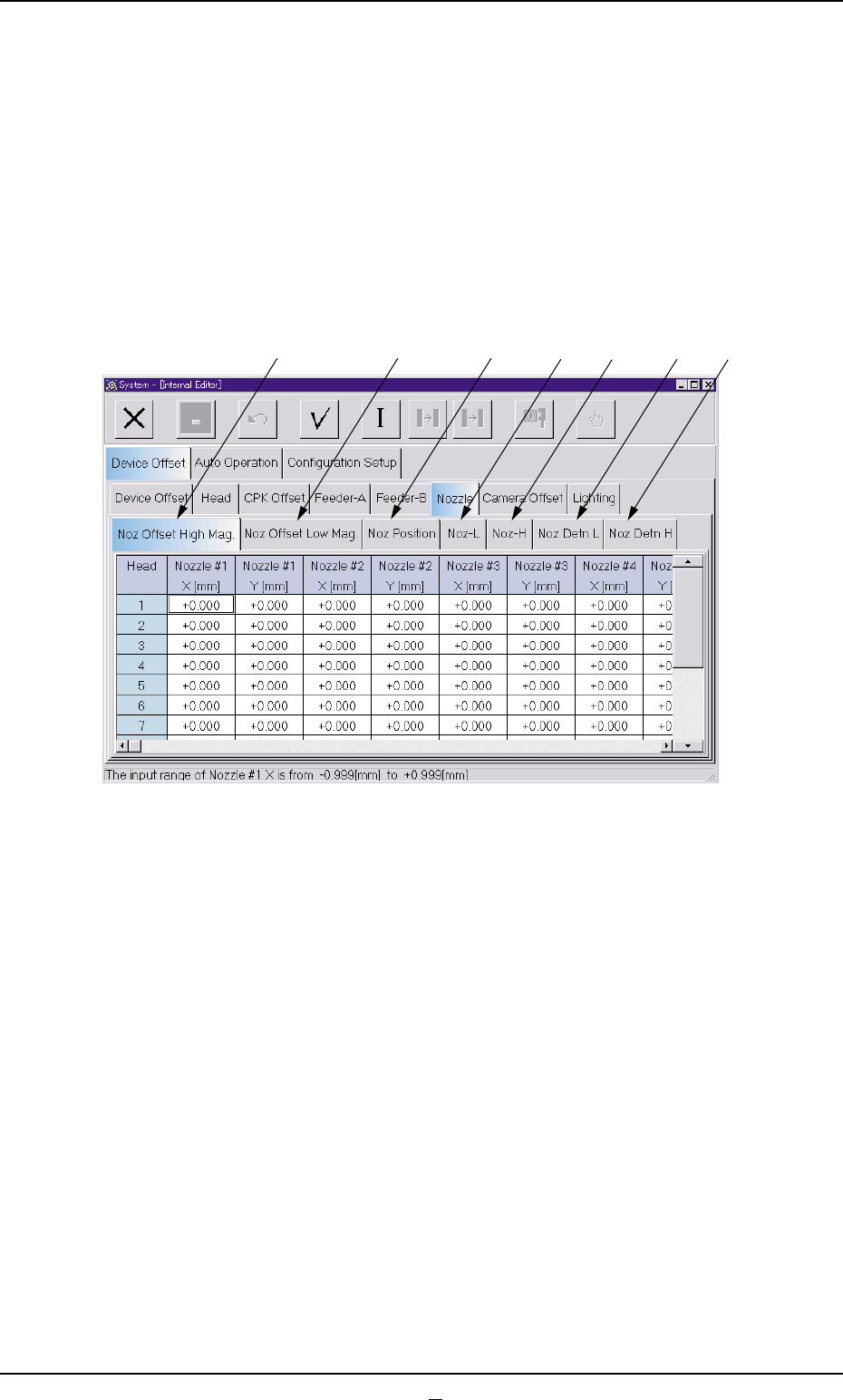
3.2.5 "Nozzle" Tab
The "Nozzle" tab sheet is composed of the "Nozzle Offset High Mag.",
"Nozzle Offset Low Mag.", "Nozzle Position", "Nozzle-L", and "Nozzle-
H" tabs.
• Sheet Layout
When the "Nozzle" tab is pressed in the "Device Offset" tab sheet, the
following tab sheet appears.
Fig. 3E28
0403-002 5-29 AIL01EDTP
3.2 "Device Offset" Tab
*1
*2
*3
*4
*5
*6
*7