3OM-1003-005.pdf - 第295页
*9 Feeder standby position F1 [mm], F2 [mm] Shown are the offset values (differences between the values of the feeder standby position and the actually measured values of the feeder axis origin position). Fig. 3E18 *10 I…
*7 Feeder carriage connection 1-2 [mm]
This is the offset data used to adjust the space between the two
feeder carriages when connected.
Reserved Data
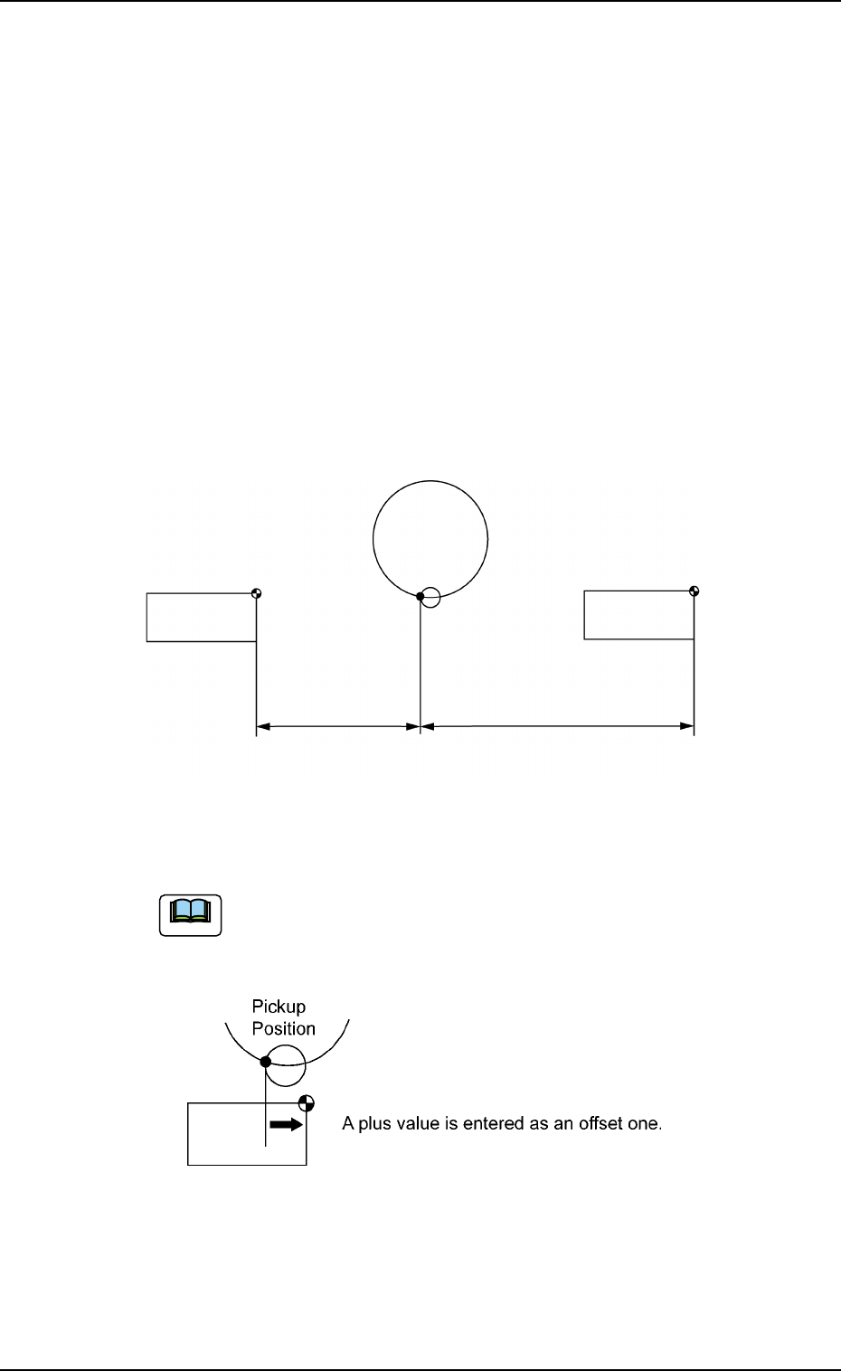
*8 Feeder carriage 1 X (Horizontal) [mm], Y (Vertical) [mm], L
(Height) [mm], 2 X (Horizontal) [mm], Y (Vertical) [mm], L (Height)
[mm]
This is the offset data used to adjust the positional distances be-
tween the component pickup position and the feeder carriages.
X [mm] (Horizontal) : Horizontal Position Data
Y [mm] (Vertical) : Vertical Position Data
L [mm] (Height) : Pickup Height Position Data
Fig. 3E16
Plus parameters entered in these text boxes increase the
travel of the feeder carriages in the "Fdr. No." direction from
the component pickup position.
Fig. 3E17
0305-001 5-15
AIL01EDTP
3.2 "Device Offset" Tab
Pickup
Position
Feeder Carriage #2
FDR. 201 at Origin
Feeder Carriage #1
FDR. 101 at Origin
#2
#1
Note
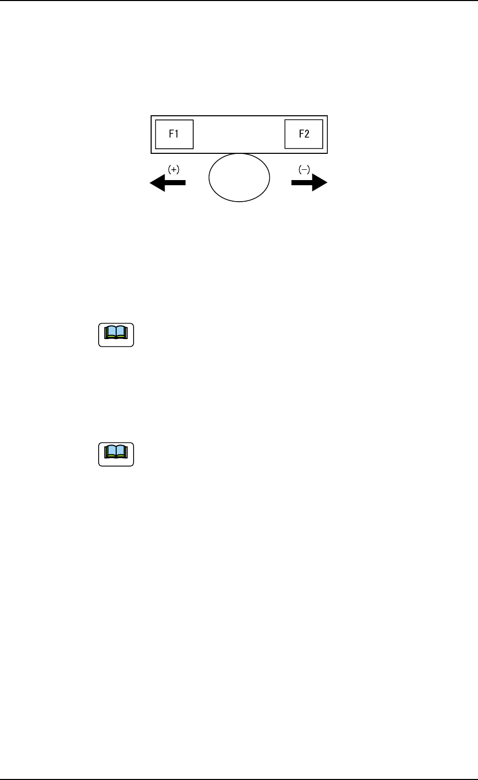
*9 Feeder standby position
F1 [mm], F2 [mm]
Shown are the offset values (differences between the values of the
feeder standby position and the actually measured values of the
feeder axis origin position).
Fig. 3E18
*10 Input conveyor width [mm]
This is the offset value indicating the difference between P.C.B. Di-
mension Y and the actually measured conveyor width.
The actual value is measured after the conveyor width is
changed when the clearance data and device offset are re-
garded as "0" (zero).
*11 Output conveyor width [mm]
This is the offset value indicating the difference between P.C.B. Di-
mension Y and the actually measured conveyor width.
The actual value is measured after the conveyor width is
changed when the clearance data and device offset are re-
garded as "0" (zero).
0403-002 5-16
AIL01EDTP
3.2 "Device Offset" Tab
Note
Note

0305-001 5-17 AIL01EDTP
*12 X/Y table chute width [mm]
This is the offset value indicating the difference between the chute
width of the X/Y table and the actually measured value.
(a) Measure the actual value at the P.C.B. outlet/input sec-
tions (fixed sections). Do not perform the measure-
ment at the roller position of the slide block.
(b) The actual value should be measured after the con-
veyor width is changed when the clearance data and
device offset are regarded as "0" (zero).
*13 Support pin up/down [mm]
This is the offset value indicating the difference between the P.C.B.
thickness and the length of the support pin (actually measured value).
*14 Unit P.C.B. B.B.R. (Option)
X [mm], Y[mm]
This is the offset data used to correct the positional deviation of the
unit P.C.B. B.B.R. detection sensor.
X [mm] : Positional Correction Data in Horizontal Direction
Y [mm] : Positional Correction Data in Vertical Direction
3.2 "Device Offset" Tab
Note