3OM-1003-005.pdf - 第143页
Order of Component Placement The machine starts the placement operation with the components that require less deceleration rate (deceleration of X/Y table move- ment) as follows. Pattern 1 (C1 Æ C2) Æ Pattern 2 (C1 Æ C2)…
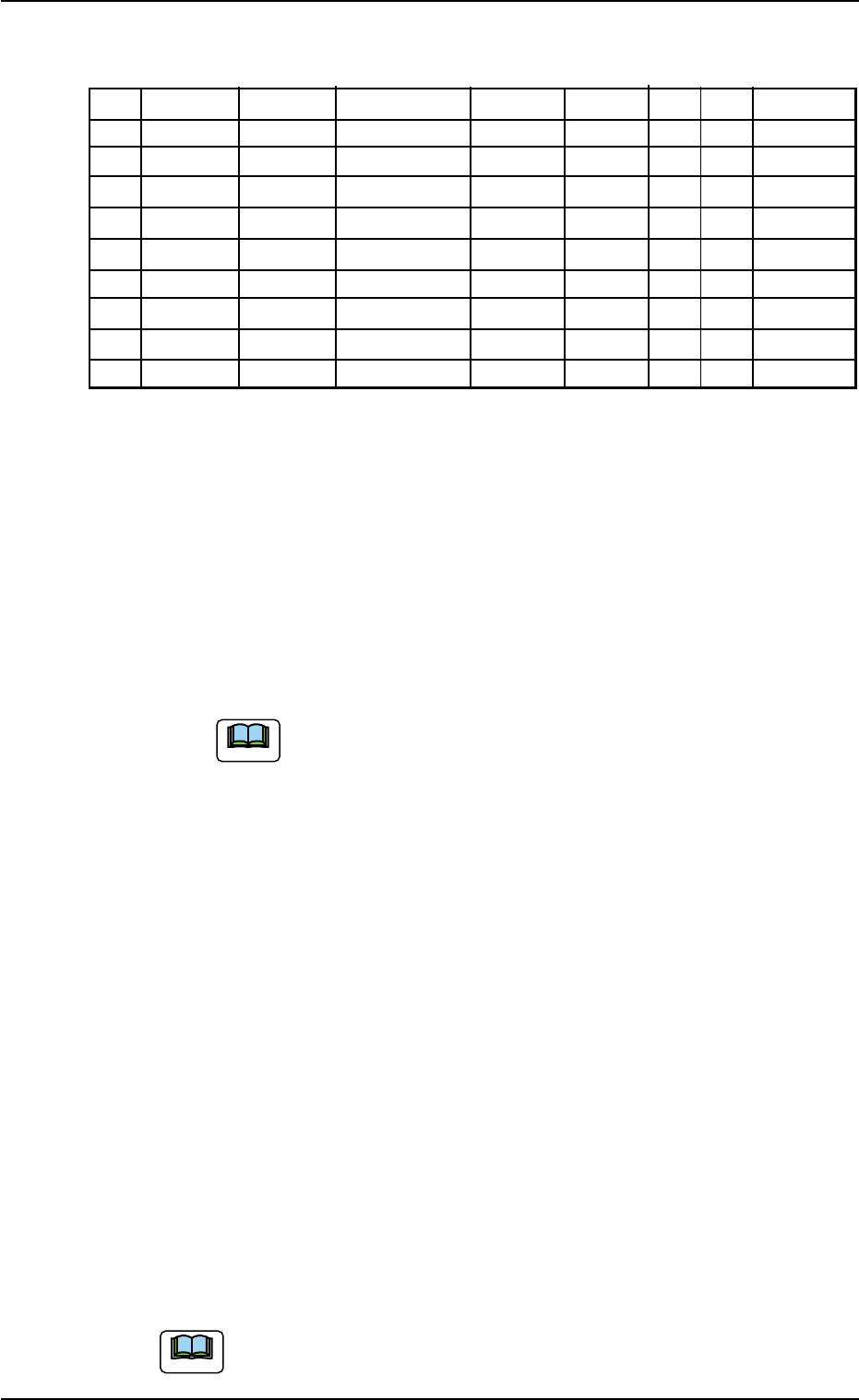
(2) Creation of Placement Data (P-data)
Table 3B34
P-No. X [mm] Y [mm] Z = theta [deg] H [mm] Fdr. No. V C Comment
1 X
1
Y
1
Z
1
+0.000 XXX 00 - C1
2
X
2
Y
2
Z
2
+0.000 XXX 00 - C2
3 +000.000 +000.000 +000.00 +0.000 000 00 2
4 X
3
Y
3
Z
3
+0.000 XXX 00 - C3
5
X
4
Y
4
Z
4
+0.000 XXX 00 - C4
6 +000.000 +000.000 +000.00 +0.000 000 00 5
7
X
5
Y
5
Z
5
+0.000 XXX 00 - C5
8
X
6
Y
6
Z
6
+0.000 XXX 00 - C6
9 +000.000 +000.000 +000.00 +0.000 000 00 P
Procedure
(2-1) Classify the components into some pairs of groups that indi-
vidually require the same speeds of the X/Y table movement.
Allocate a pair groups of components that require the least
deceleration rate to the smallest "P-No." steps.
In this example, the parameters related to C1 and C2 are set
in the "P-No. 1" and "P-No. 2" steps.
(2-2) Set "2" in the "C" text box of the "P-No. 3" step and "0" (zero)
for the other data.
This step is handled as a delimiter of speed groups.
(a) The machine does not place any components for
the step where a delimiter of speed groups is speci-
fied.
(b) Control Command "2" does not mean that it is used
to control the speed of the X/Y table movement.
Any of the control commands (0 to 9) can be used
as a delimiter.
In this example, "2" is used to indicate that the com-
ponents in the "P-No. 4" step and the subsequent
ones require the 20% deceleration rate.
(2-3) Follow the same procedure to create each step as described
below.
• Set C3 and C4 in the "P-No. 4" and "P-No. 5" steps.
• Set "5" in the "C" text box of the "P-No. 6" step and "0" (zero)
for the other data.
• Set C5 and C6 in the "P-No. 7" and "P-No. 8" steps.
(2-4) Create the last step in the same way as a normal program. Be
sure to set "P" as a control command in the "C" text box.
Note: Actual component placement will be made in almost
the reverse sequence as explained below.
Up to 20 speed groups can be created in one pattern pro-
gram.
0305-001 2-73
AIL01EDTP
3.6 Repetitive Patterns (Block Sorting Enabled)
Note
Note
Order of Component Placement
The machine starts the placement operation with the components
that require less deceleration rate (deceleration of X/Y table move-
ment) as follows.
Pattern 1 (C1 Æ C2) Æ Pattern 2 (C1 Æ C2) Æ Pattern 3 (C1 Æ C2) Æ
Pattern 3 (C3 Æ C4) Æ Pattern 2 (C3 Æ C4) Æ Pattern 1 (C3 Æ C4) Æ
Pattern 1 (C5 Æ C6) Æ Pattern 2 (C5 Æ C6) Æ Pattern 3 (C5 Æ C6) Æ
Placement Data (O-data)
Follow the normal procedure to create this data.
Placement-Speed-Related Component Library Data
The following component library data also gives some effect to the
placement speed. (For your reference)
Speed Data: Pick-Up [sec], Rotary turret [sec], Placement [sec]
Feeder carriage, Recognition time [sec]
Refer to "COMPONENT LIBRARY (TCM-X Series)" for de-
tails of each speed data. (Another Instruction Manual)
0305-001 2-74
AIL01EDTP
3.6 Repetitive Patterns (Block Sorting Enabled)
Note
3.7 Repetitive Patterns (Polar Coordinate
Conversion Function)
Follow the same procedure as described in "3.4 Repetitive Patterns
(Unit P.C.B. B.B.R. Enabled)" except for "Placement Data (O-data)".
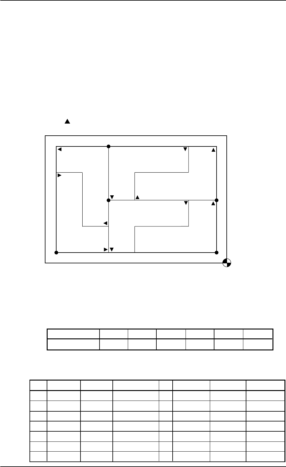
(1) Information on Pattern Program Creation
• Example of Patterns
Fig. 3B134
• Coordinates of Each Pattern Origin
Table 3B35
Pattern Origins O
1
O
2
O
3
O
4
O
5
O
6
Coordinates (X
1
,Y
1
)(X
2
,Y
2
)(X
1
,Y
2
)(X
2
,Y
3
)(X
2
,Y
3
)(X
3
,Y
1
)
(2) Creation of Placement Data (O-data)
Table 3B36
O-No. X [mm] Y [mm] Z = theta [deg] C Comment B-X [mm] B-Y [mm]
1
X
1
Y
1
+000.00 - +000.000 +000.000
2 X
2
Y
2
+180.00 - +000.000 +000.000
3 X
1
Y
2
+000.00 - +000.000 +000.000
4 X
2
Y
3
+180.00 - +000.000 +000.000
5 X
2
Y
3
+090.00 - +000.000 +000.000
6 X
3
Y
1
+270.00 - +000.000 +000.000
7 +000.000 +000.000 +000.00 E +000.000 +000.000
0305-001 2-75 AIL01EDTP
Placement Coordinate
Reference Point
O
4
O
1
O
3
O
2
O
6
Pattern 4 (180°)
Pattern 2 (180°)
Pattern 6
(270°)
Pattern 5
(90°)
Pattern 3 (0°)
Pattern 1 (0°)
O
5
is a fiducial mark.
Assume that Pattern 1 is "0°".
3.7 Repetitive Patterns (Polar Coordinate Conversion Function)