3OM-1003-005.pdf - 第120页
(C02_09) C Enter some of the following control commands. If a control command other than the following ones is used, the step becomes invalid. - (hyphen) : This command handles the steps as those for com- ponent placemen…
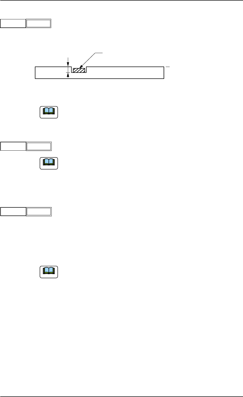
(C02_06) H [mm]
Set the height of components to be placed.
(Reserved Data)
Unit: mm
Fig. 3B102
Do not set any height in the last line (last P-No.).
Keep it as "+0.000".
(C02_07) Fdr. No.
Set the Nos. of the feeders loaded with components.
(a) The feeder Nos. (Fdr Nos.) to be set here must be specified in the
placement feeder location data.
(b) Do not set any feeder No. in the last line (last step No.).
Keep it as "000".
(C02_08) V
Select one of the following options as the data for the local recogni-
tion mode.
00 : The local recognition is not performed.
01 : The local recognition (1-point recognition) is performed.
02 : The local recognition (2-point recognition) is performed.
(a) Be sure to set "Enable" in the "P.E.C. recognition mode
local" before specifying a parameter in the "V" text box.
Refer to "(A02_01) P.E.C. recognition function" in "Opera-
tion Data" for details.
(b) Refer to"(C02_11)", "(C02_12)", and "(C02_13)" for how
to specify the X and Y locations and the mark codes of the
local P.E.C. recognition mode.
P.C.B.
Component
Reference Plane
H
0305-001 2-50 AIL01EDTP
101Fdr. No.
Fig. 3B103
2.5 Placement Data
+0.000
H [mm]
Fig. 3B101
-
V
Fig. 3B104
Note
Note
Note
(C02_09) C
Enter some of the following control commands.
If a control command other than the following ones is used, the step
becomes invalid.
- (hyphen) : This command handles the steps as those for com-
ponent placement.
S:This command invalidates the steps specified as those
for component placement.
C:This command invalidates the steps specified as those
for component placement.
Note: As for dispensers, these steps become invalid.
D:This command handles the steps as those for com-
ponent placement.
Note: As for dispensers, these steps become invalid.
E:When placement data (O) is not created, this shows
the end of the steps in the placement data (P).
P:This shows the end of the steps in the placement data
(P) of a repetitive pattern program.
Components are placed in normal sequence.
Q:This shows the end of the steps in the placement data
(P) of a repetitive pattern program.
Components are placed in reverse sequence.
B:When the unit P.C.B. B.B.R. detection function (op-
tion) must be used, set this control command in the P-
No. 1 step.
See Note (a).
0, 1, 2, 3, 4, 5, 6, 7, 8, 9:
These control commands are used to enable the block
sorting function.
See Note (b).
(a) Do not set the B command in any lines except "P-No. 1".
Refer to "3.5 Repetitive Patterns (Unit P.C.B. B.B.R. Function En-
abled)" for concrete examples of the unit P.C.B. B.B.R. detection
function (option).
2.5 Placement Data
0412-002 2-51 AIL01EDTP
-
C
Fig. 3B105
Note
Notice
(b) Block Sorting FunctionWhen components requiring different tact time
(different X/Y table speeds) are used in a repetitive pattern program
and unit P.C.B.'s are finished one by one in normal sequence, the
tact time of component placement on the second and subsequent
multi-unit P.C.B.'s is reduced to the lowest one of the first unit P.C.B.,
greatly deteriorating the productivity.However, this block sorting func-
tion can be used to place high-speed components (components to
be placed at high speed) first of all the others on all unit boards of a
multi-unit P.C.B., improving productivity.Refer to "3.6 Repetitive Pat-
terns (Block Sorting Enabled)" for a concrete example.
(c) Confirm that "0" (zero) is set in the "X [mm]", "Y [mm]", "Z=theta", "H
[mm]", and "Fdr No." text boxes of the last line (last step No.) and set
"E", "P", or "Q".
(C02_10) Comment
Set a comment for each step No.
Up to 32 characters (alphanumerics and marks) can be used.
(a) The automatic operation is not affected by these comments.
(b) The comments can be used to check "Ref. No." printed on the upper
surfaces of P.C.B’s.
(C02_11) X1 [mm], Y1 [mm]
Set the coordinates of the first fiducial mark for the local recognition
mode in each text box.
Unit: mm
(C02_12) X2 [mm], Y2 [mm]
Set the coordinates of the second fiducial mark for the local recogni-
tion mode in each text box.
Unit: mm
(C02_13) FM1, FM2
Set parameters for "FM1" (First Fiducial Mark No.) and "FM2" (Sec-
ond Fiducial Mark No.) related to the local recognition mode.
Select the mark Nos. (Mark #) specified in the P.E.C. recognition mark
data of the operation data.
2.5 Placement Data
0305-001 2-52 AIL01EDTP
Comment
Fig. 3B106
Fig. 3B107
X1 [mm]
Y1 [mm]
010.000
010.000
Fig. 3B108
X2 [mm]
Y2 [mm]
050.000
050.000
Fig. 3B109
FM1
FM2
01
01
Note