3OM-1003-005.pdf - 第271页
• "Head Bypass Factor" T ab Sheet Fig. 3D21 "Head Nozzle Bypass Data" T ab Sheet ("Head Bypass Factor" T ab Sheet) 5.1 "Head Nozzle Bypass Data" T ab 0305-001 4-46 AIL01EDTP
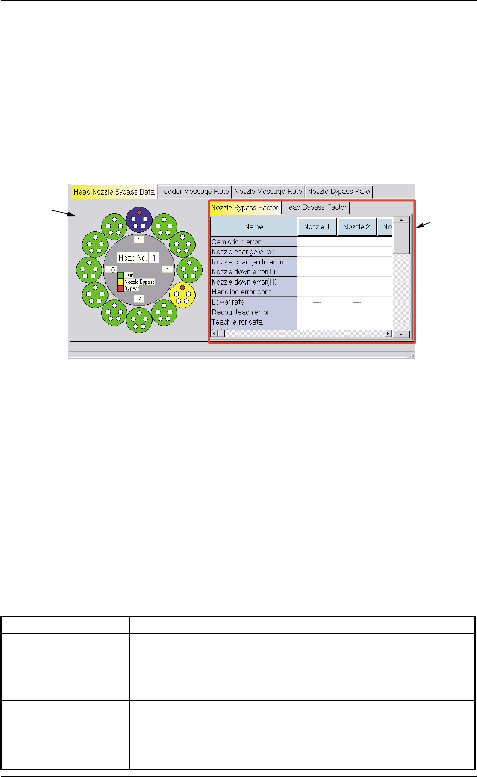
5.1 "Head Nozzle Bypass Data" Tab
The corresponding tab sheet displays the bypass factors of the heads
or the nozzles.
• Sheet Layout
When the "Head Nozzle Bypass Data" tab is pressed in the "Bypass
& Rate Data" window, the following tab sheet appears inside the win-
dow.
Fig. 3D20 "Head Nozzle Bypass Data" Tab Sheet
("Nozzle Bypass Factor" Tab Sheet)
• Sheet Composition
*1 Graphical Expression of Heads and Nozzles
When a head (nozzles) is selected on the graphical rotary turret,
the bypass factors are displayed on the right tab sheet.
*2 Tabs and Tab Sheets
The right side of the "Head Nozzle Bypass Data" tab sheet is occu-
pied by the following two tab sheets.
Table 3D7
Tabs Description
Nozzle Bypass Factor When this tab is selected, the nozzles are expressed graphically on
the left side and the nozzle bypass factors are indicated on the right
tab sheet.
(See Fig. 3D20.)
Head Bypass Factor When this tab is selected, the heads are expressed graphically on
the left side and the head bypass factors are indicated on the right
tab sheet.
(See Fig. 3D21.)
*1
*2
5.1 "Head Nozzle Bypass Data" Tab
0305-001 4-45 AIL01EDTP
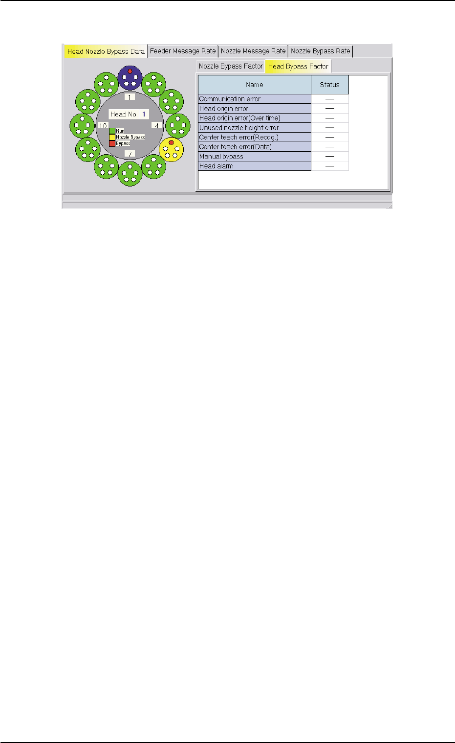
• "Head Bypass Factor" Tab Sheet
Fig. 3D21 "Head Nozzle Bypass Data" Tab Sheet
("Head Bypass Factor" Tab Sheet)
5.1 "Head Nozzle Bypass Data" Tab
0305-001 4-46 AIL01EDTP
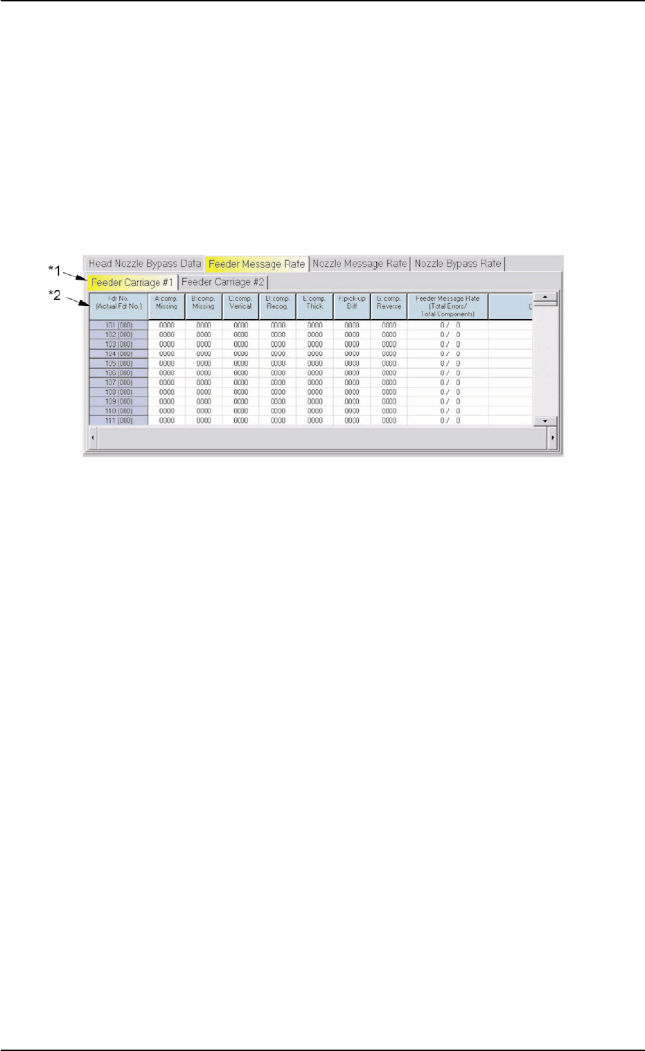
5.2 "Feeder Message Rate" Tab
The corresponding tab sheet displays the pick-up rates (managed for
each individual feeders) based on the feeder message rates specified
in the auto operation setup data.
• Sheet Layout
When the "Feeder Message Rate" tab is pressed in the "Bypass & Rate
Data" window, the following tab sheet appears inside the window.
Fig. 3D22 "Feeder Message Rate" Tab Sheet
• Sheet Composition
*1 Tabs
The "Feeder Message Rate" tab sheet is divided further into two tab
sheets and each tab sheet shows the handling errors per feeder on
each individual feeder carriages.
When a tab is pressed, the corresponding tab sheet appears, indi-
cating that the related feeder carriage is selected.
*2 Items
The following items are displayed.
(1) [Fdr No. (Actual Fdr No.)] Button
Shown are the feeder Nos.
(2) [A: comp. Missing] Button
Each text box shows the total number of missing components de-
tected by the linear measure detection sensor for each individual
feeders.
5.2 "Feeder Message Rate" Tab
0305-001 4-47 AIL01EDTP