3OM-1003-005.pdf - 第71页
1.1.1 Outline of V arious Data The pattern program is composed of the following data. Operation Data: This data is used to generally manage the pattern program data. Placement Feeder Location Data: This data is used to s…
1. Outline of Pattern Program
1.1 Composition of Pattern Program
The pattern program is composed of the following data.
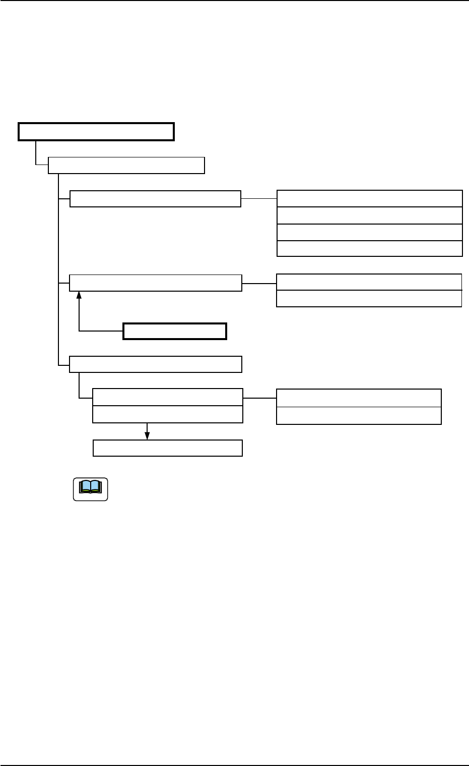
Pattern Program (Section 2)
Pattern Program Name (2.2)
Operation Data (2.3) P.C.B. Data (A01)
P.C.B. Recognition Data (A02)
P.C.B. Recognition Mark Data (A03)
Setup Data (A04)
Placement Feeder Location (2.4) Feeder Carriage #1 (B01)
Feeder Carriage #2 (B01)
Component IDs
Component Library
Placement Data (2.5)
Placement Data U01 (C01) Placement Data (P) (C02)
Placement Data U02 (C01)
Placement Data (O) (C03)
Placement Data Un (C01)
"(2.2) through (2.4), "(A01) through (A04)", "(B01)", and "(C01)
through (C03)" show the item Nos. to be referred to.
Fig. 3B1 Composition of Pattern Program
0305-001 2-1
AIL01EDTP
1. Outline of Pattern Program
Note

1.1.1 Outline of Various Data
The pattern program is composed of the following data.
Operation Data:
This data is used to generally manage the pattern program data.
Placement Feeder Location Data:
This data is used to set parameters which determine a compo-
nent ID (type) to be allocated to each feeder slot No. (Fdr. No.).
Placement Data:
The set parameters (designation of coordinates and direction)
are used for placement of components allocated in the place-
ment feeder location data.
1.1.2 Input Procedure of Each Data
Refer to "4. "Pattern Program" Edit Window" for detailed information on
how to enter each parameter.
After entering each parameter, using the network terminal (option), send
it to the main machine.
Pattern Program Data Sheets
Make use of the pattern program data sheets described in "Sec-
tion 6".
1.1 Composition of Pattern Program
Note
0305-001 2-2 AIL01EDTP

1.2 Composition of Operation Data
This data is used to generally manage the pattern program data.
This data is composed of the P.C.B. data, the P.C.B. recognition data,
the P.C.B. recognition mark data, and the setup data.
Refer to "2.3 Operation Data" in "Section 2" for details.
A01 P.C.B. Data Table 3B1
Reference No. Labels
A01_01 Comment 1, 2
A01_02 P.C.B. size
A01_03 P.C.B. origin offset
A01_04 Placement Angle
A01_05 P.C.B. height offset
A01_06 P.C.B. positioning reference
A01_07 Pre-Placed component thickness
A01_08 Placement mode
A01_09 P.C.B. transfer speed
A01_10 Placement data sorting
A01_11 Feeder standby position
A01_12 Alternate mode
A01_13 Feeder No. offset
A01_14 X/Y table accel des
A01_15 C1, C2 accel des
A01_16 Recovery regulation
A01_17 Unit P.C.B. B.B.R (Option)
A01_18 Overall P.C.B. B.B.R (Option)
A02 P.C.B. Recognition Data Table 3B2
Reference No. Labels
A02_01 P.E.C. recognition function
A02_02 P.E.C. recognition mode global
051 1-002 2-3
AIL01EDTP
1.2 Composition of Operation Data