3OM-1003-005.pdf - 第293页
*2 Camera X Theta [deg], Y Theta [deg] This is the offset data for angle difference between the camera X and Y axis and the scanning coordinates X and Y of the component recognition camera (Camera 1: high magnification).…
• Sheet Composition
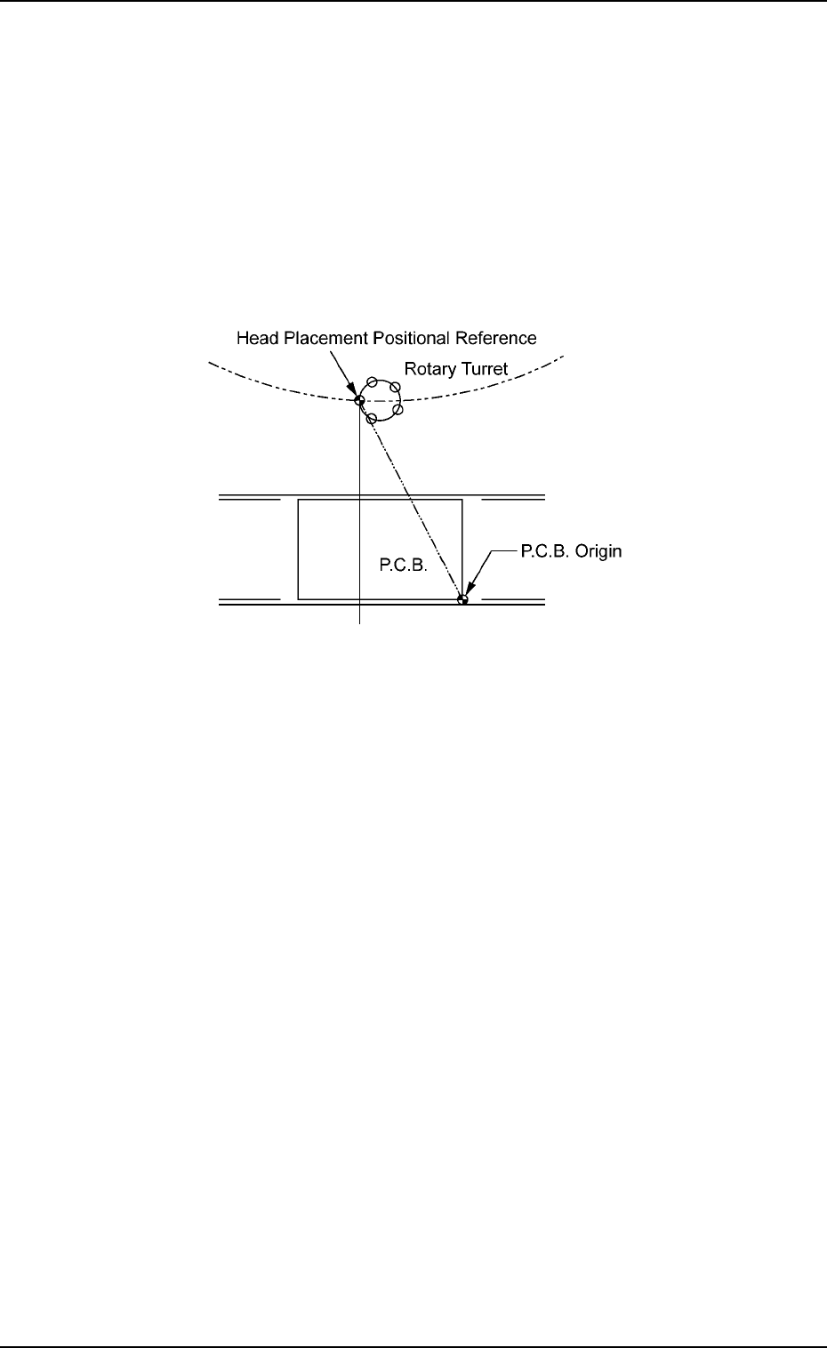
*1 X/Y table X [mm] (Horizontal), Y [mm] (Vertical)
This is the offset data between the X/Y table origin and the positional
reference of the head’s component placement.
When the X/Y table is at its origin, the distance between the P.C.B.
origin and the positional reference (reference head position) for com-
ponent placement performed by a nozzle on the No. 1 head should
be set to adjust the data compared with the design values.
Fig. 3E14
0305-001 5-13
AIL01EDTP
3.2 "Device Offset" Tab
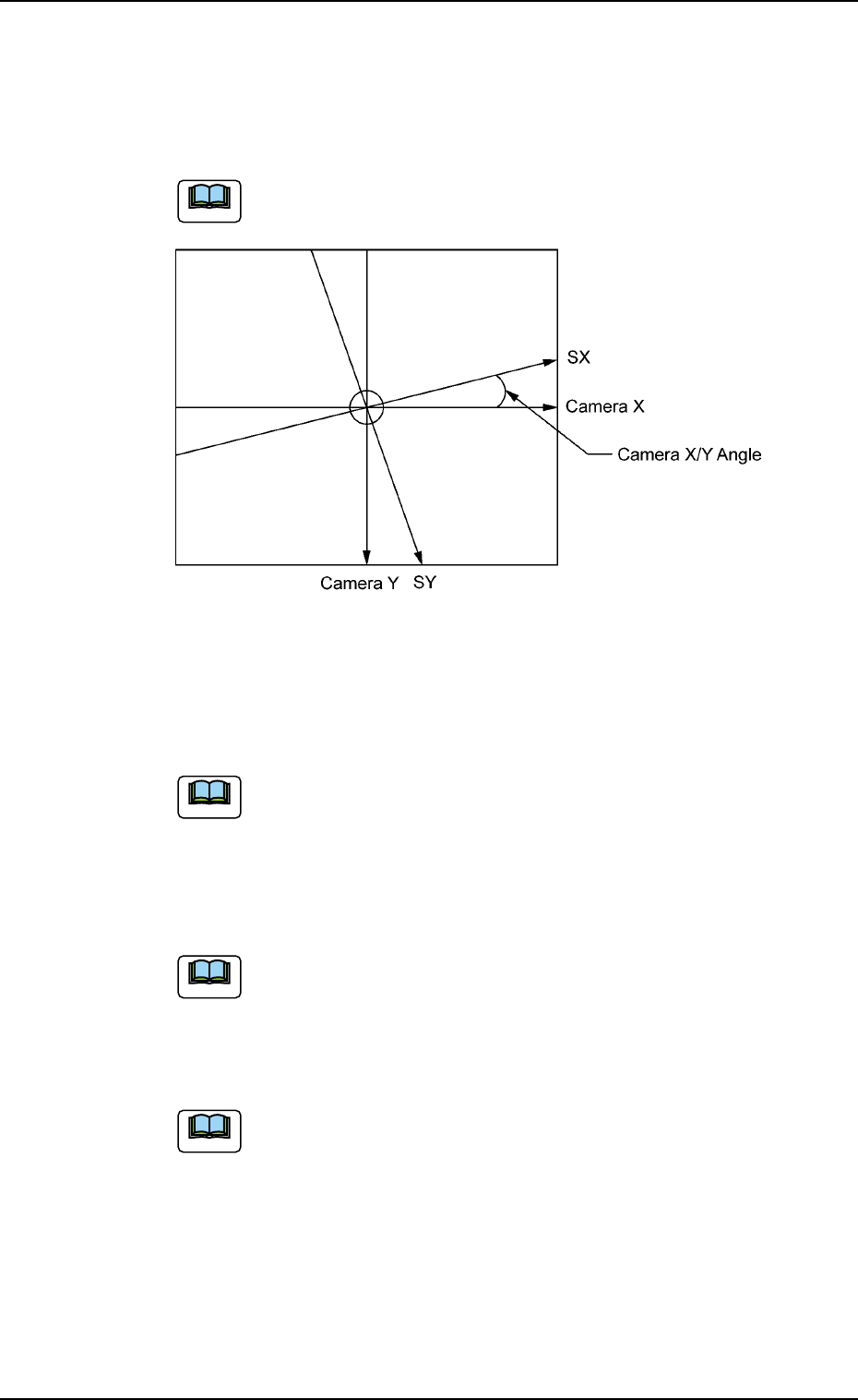
*2 Camera X Theta [deg], Y Theta [deg]
This is the offset data for angle difference between the camera X
and Y axis and the scanning coordinates X and Y of the component
recognition camera (Camera 1: high magnification).
The parameters are computed using the jig nozzle.
Fig. 3E15
*3 Component pickup (Z) axis [mm]
This is the offset data for the origin position of the component pickup
Z axis (CZ).
A plus (+) value increases the downward movement of the
nozzle.
*4 Component placement (Z) axis [mm]
This is the offset data for the origin position of the component place-
ment Z axis (MZ).
A plus (+) value increases the downward movement of the
nozzle.
*5 P.C.B. transfer Left [mm], Right [mm]
This is the offset data to adjust the feed limit at P.C.B. transfer.
This offset data is used for fine adjustment of the transfer
stroke.
*6 Master nozzle H [mm], L-L [mm], L-X [mm], L-Y [mm]
Entered are the nozzle parameters that were measured using the
master nozzle.
H:Height (H Level)
L-L : Height (L Level)
L-X : X in L Level
L-Y : Y in L Level
0305-001 5-14
AIL01EDTP
3.2 "Device Offset" Tab
Note
Note
Note
Note
*7 Feeder carriage connection 1-2 [mm]
This is the offset data used to adjust the space between the two
feeder carriages when connected.
Reserved Data
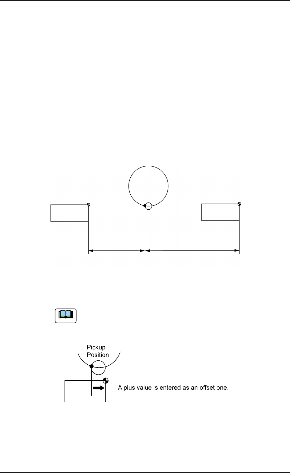
*8 Feeder carriage 1 X (Horizontal) [mm], Y (Vertical) [mm], L
(Height) [mm], 2 X (Horizontal) [mm], Y (Vertical) [mm], L (Height)
[mm]
This is the offset data used to adjust the positional distances be-
tween the component pickup position and the feeder carriages.
X [mm] (Horizontal) : Horizontal Position Data
Y [mm] (Vertical) : Vertical Position Data
L [mm] (Height) : Pickup Height Position Data
Fig. 3E16
Plus parameters entered in these text boxes increase the
travel of the feeder carriages in the "Fdr. No." direction from
the component pickup position.
Fig. 3E17
0305-001 5-15
AIL01EDTP
3.2 "Device Offset" Tab
Pickup
Position
Feeder Carriage #2
FDR. 201 at Origin
Feeder Carriage #1
FDR. 101 at Origin
#2
#1
Note