3OM-1003-005.pdf - 第217页
3.4 "Control Data" T ab 051 1-002 3-32 AIL01EDTP 3 . 4 "Control Data" T ab The corresponding tab sheet appears when "Cylindrical", "Square", "De- form (Simple)", "IC…
3.3 "Recognition Data" Tab
051 1-002 3-31 AIL01EDTP
*7 Outward length detn
Outward length tol [mm]
When "Enable (Mnl)" is set in the "Outward length detn" text box,
it is required to enter a parameter in the text box.
When "Connector (Simple)", "Connector (Complex)", "Other
Leaded (Simple)", or "Other Leaded (Complex)" is selected
in the "Component shape" text box, "Outward length detn"
does not appear.
*8 Lead width detn
Lead width tol [mm]
When "Enable (Mnl)" is set in the "Lead width detn" text box, it is
required to enter a parameter in this text box.
When "Connector (Simple)", "Connector (Complex)", "Other
Leaded (Simple)", or "Other Leaded (Complex)" is selected
in the "Component shape" text box, "Outward length detn"
does not appear.
*9 Lead posn (Latl dir) detn
Lead posn (Latl dir) tol [mm]
When "Enable (Mnl)" is set in the "Lead posn (Latl dir) detn" text
box, it is required to enter a parameter in this text box.
Note
Note
3.4 "Control Data" Tab
051 1-002 3-32 AIL01EDTP
3.4 "Control Data" Tab
The corresponding tab sheet appears when "Cylindrical", "Square", "De-
form (Simple)", "IC (Simple)", "IC (Complex)", "Connector (Simple)",
"Connector (Complex)", "Other Leaded (Simple)", or "Other Leaded
(Complex)" is selected in the "Component shape" text box.
• Sheet Layout
When the "Control Data" tab is pressed, the "Control Data" tab sheet
appears.
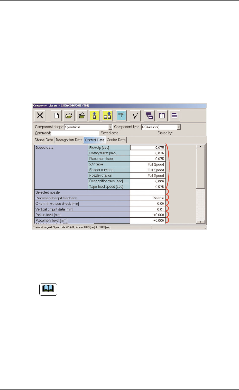
Fig. 3C22 "Control Data" Tab Sheet ("Cylindrical" Selected)
• Sheet Composition
Enter a parameter in the text box.
Refer to "4.1.3 Basic Usage of Text Boxes" (Section 2) for the
detailed information on how to enter each parameter.
*1 Speed Data, *2 Selected nozzle,
*3 Placement height feedback, *4 Cmpnt thickness check [mm],
*5 Vertical cmpnt data [mm], *6 Pickup level [mm],
*7 Placement level [mm],
Note
*2
*1
*3
*4
*5
*6
*7
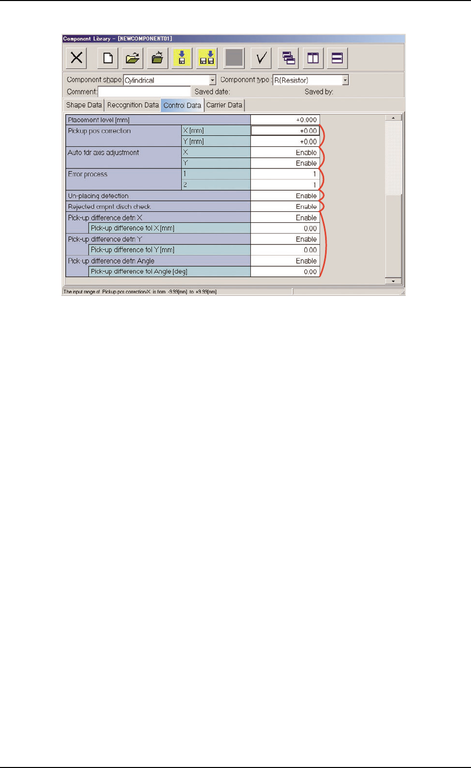
Fig. 3C23 "Control Data" Tab Sheet ("Cylindrical" Selected)
*8 Pickup pos correction, *9 Auto fdr axis adjustment,
*10 Error process, *11 Un-placing detection,
*12 Rejected cmpnt disch check
*13 Pick-up difference detn X, Y, Angle
Pick-up difference tol X [mm], Y [mm], Angle [deg]
When "Enable" is set in the "Pick-up difference detn X", "Pick-up
difference detn Y", and/or "Pick-up difference detn Angle" text box,
it is required to enter a parameter in the corresponding text box.
*9
*8
*10
*13
*12
*11
3.4 "Control Data" Tab
051 1-003 3-33 AIL01EDTP