3OM-1003-005.pdf - 第202页
3 .2 "Shape Data" T ab 3.2.1 "Mold Size" T ab The corresponding tab sheet appears when "Cylindrical", "Square", "De- form (Simple)", "IC (Simple)", "IC Com…

*2 Edit Sheet
This sheet enables the operator to edit the parameters of the se-
lected component ID.
3.1 Toolbar and Icons
051 1-002 3-16 AIL01EDTP
3.2 "Shape Data" Tab
3.2.1 "Mold Size" Tab
The corresponding tab sheet appears when "Cylindrical", "Square", "De-
form (Simple)", "IC (Simple)", "IC Complex", "Connector (Simple)", "Con-
nector (Complex)", "Other Leaded (Simple)", or "Other Leaded (Com-
plex)" is selected in the "Component shape" text box.
• Sheet Layout
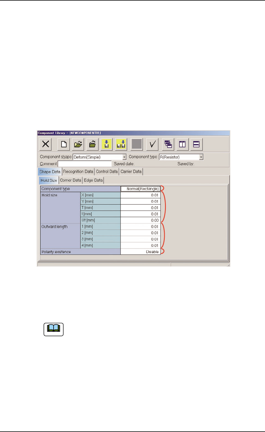
When the "Mold Size" tab is pressed in the "Shape Data" tab sheet,
the following tab sheet appears.
Fig. 3C13 "Shape Data" Tab Sheet ("Deform (Simple)" Selected)
• Sheet Composition
Each parameter is displayed or can be entered.
Refer to "4.1.3 Basic Usage of Text Boxes" (Section 2) for the
detailed information on how to enter each parameter.
(1) Component shape: Cylindrical, Square
*2 Mold size, *4 Polarity existence
3.2 "Shape Data" Tab
*1
*2
*4
*3
051 1-002 3-17 AIL01EDTP
Note

(2) Component shape: Deform (Simple)
*1 Component type, *2 Mold size, *3 Outward length,
*4 Polarity existence
(3) Component Shape: IC (Simple), IC (Complex),
Connector (Simple),
Connector (Complex),
Other Leaded (Simple),
Other Leaded (Complex)
*2 Mold size, *3 Outward length, *4 Polarity existence
3.2 "Shape Data" Tab
0305-001 3-18 AIL01EDTP