3OM-1003-005.pdf - 第333页
051 1-001 5-47-5 AIL01EDTP 3.3 "Auto Operation" T ab • Example of "Sampling Bias" Mode = Sampling Bias, Bias coefficient (X) [%] = 50, Bias coefficient (Y) [%] = 50 First Follow-Up after Component Rep…
051 1-001 5-47-4 AIL01EDTP
3.3 "Auto Operation" Tab
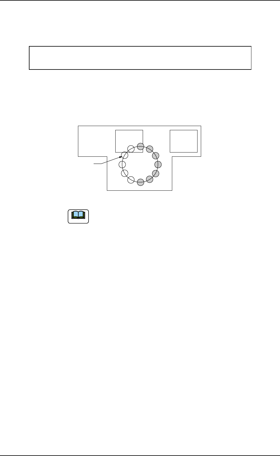
Second Follow-Up after Component Replacement
Components are picked up and recognized based on the first
corrected value as frequently as the specified number of picks.
Mean of Deviations as Results of 3-time Recognitions ×
70% (50% + 40%/2) = Calculation of Second Corrected Value
This "Second Corrected Value" is also reflected on the pickup
motions taken subsequently after "Next" in the figure.
(The third and subsequent follow-ups are the same as "Stan-
dard".)
The amount of feedback is saved in Reel Offset B.
1
2
3
Next
Fig. 3E44-2
Note
051 1-001 5-47-5 AIL01EDTP
3.3 "Auto Operation" Tab
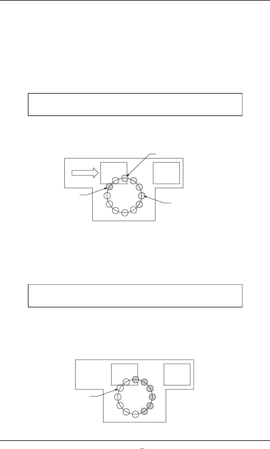
• Example of "Sampling Bias"
Mode = Sampling Bias, Bias coefficient (X) [%] = 50,
Bias coefficient (Y) [%] = 50
First Follow-Up after Component Replacement
The deviation is measured based on the first (= sample) com-
ponent recognition that was performed when a component was
picked up after component replacement.
Deviation as Result of 1-time Recognition ×
90% (50% + 40%) = Calculation of First Corrected Value
This "First Corrected Value" is reflected on the pickup motions
taken subsequently after "Next" in the figure.
Second Follow-Up after Component Replacement
The deviations are measured based on the component recogni-
tions that were performed twice (the number of component picks)
with the first corrected value.
Mean of Deviations as Results of 2-time Recognitions ×
70% (50% + 40%/2) = Calculation of Second Corrected Value
This "Second Corrected Value" is also reflected on the pickup
motions taken subsequently after "Next" in the figure.
(The third and subsequent follow-ups are the same as "Stan-
dard".)
1
Next
Fig. 3E44-3
Component
Recognition
Component Pickup
1
2
Next
Fig. 3E44-4

0305-001 5-48 AIL01EDTP
*5 Feeder message rate
Error counts [times], # of picks [times]
Set the parameters to show the feeder slot No. (Fdr. No.) of the tape
feeder whose pickup rate has deteriorated during automatic opera-
tion.
When the number of picks has reached the specified value, the
parameter in the "Error counts [times]" text box is cleared.
When the number of pickup errors has reached the specified error
counts before the number of picks reaches the specified number of
picks, a warning message is issued as machine information.
(a) The number of picks and pickup errors is managed for
each feeder slot No. but the parameters in the "Error counts
[times]" and "# of picks [times]" text boxes are equally re-
flected on every feeder slot No.
(b) The data input range is "0 to 9999" (times) for both "Error
counts [times]" and "# of picks [times]".
(c) When "0" (zero) is set for "# of picks [times]" and "Error
counts [times]" or the parameter in the "Error counts
[times]" text box is larger than the parameter in the "# of
picks [times]" text box, no warning message is issued.
3.3 "Auto Operation" Tab
Note