3OM-1003-005.pdf - 第86页
(A01_06) P .C.B. positioning reference Displayed is a P .C.B. positioning reference point. Rear Left : P .C.B.’s are positioned based on the rear left corners. Front Left : P .C.B.’s are positioned based on the front lef…
(A01_04) Placement Angle
"Relative" or "Absolute" can be selected as an angle value
in the text box.
Relative
The normal placement direction is selected.
Absolute
When the component feeding direction differs from one as-
sumed in the component library, it is required to change only
the feeding direction in the component library data. It is not
necessary to change the placement direction in the pattern
program data.
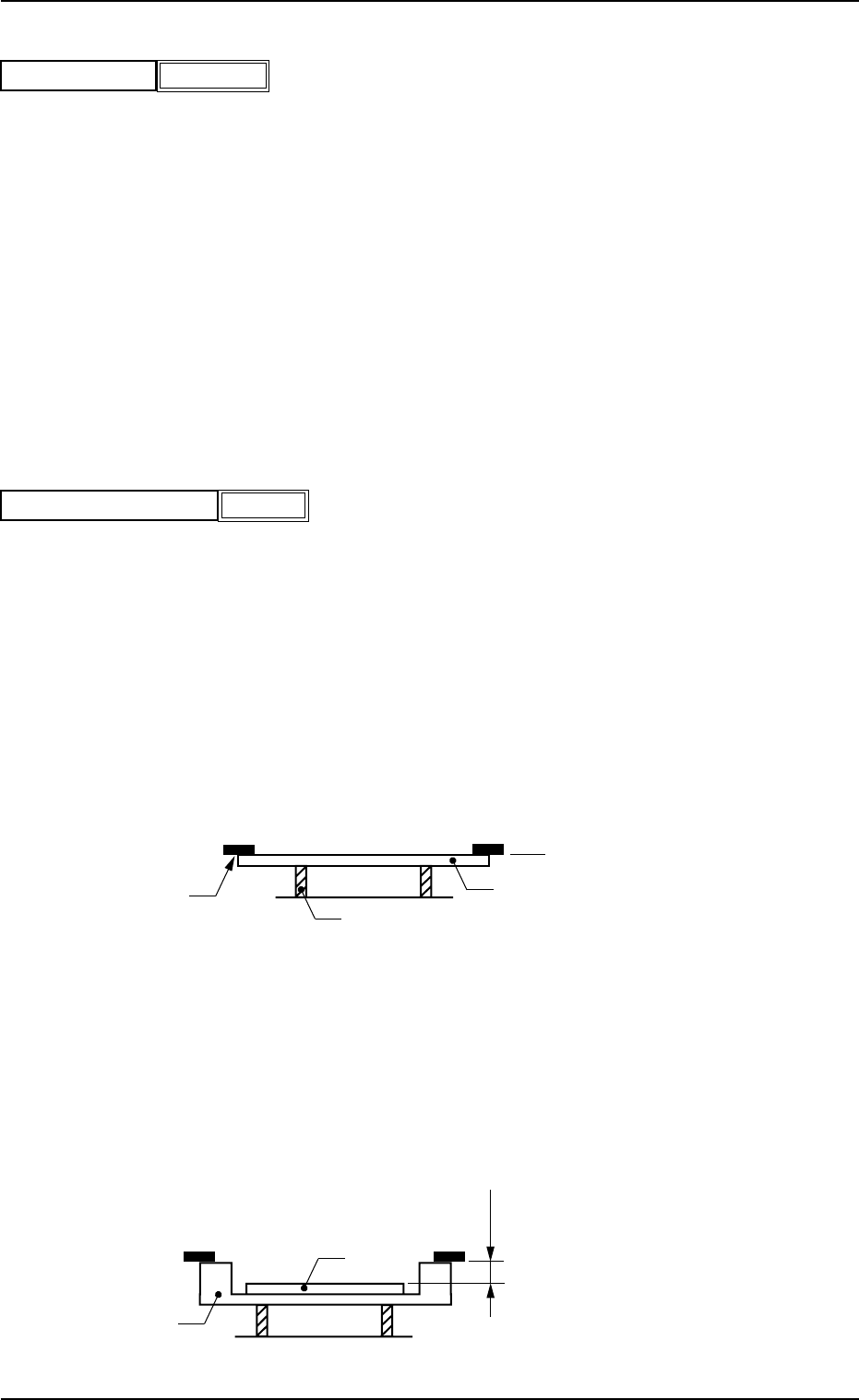
(A01_05) P.C.B. height offset
Set an offset value as a nozzle descending distance based on the
upper surface of the P.C.B. in the component placement section.
This offset value applies to all components in the pattern program.
Unit: mm
Normal Cases
Set "0.000 mm" (zero) in the text box.
The figure below shows that the upper surface of a P.C.B. is main-
tained at the P.C.B. upper surface reference point by the P.C.B. sup-
port pins.
Fig. 3B18
Example of Jig P.C.B. Usage
The figure below shows that the upper surface of a P.C.B. is lower
than the P.C.B. upper surface reference point.
If "+a mm" is set as an offset value at this time, components can be
placed correctly on the P.C.B.
Fig. 3B19
P.C.B. Upper Surface
Reference Plane
P.C.B.
Chute
P.C.B. Support Pin
P.C.B.
Jig P.C.B.
a mm
P.C.B. Upper Surface
Reference Plane
051 1-002 2-16 AIL01EDTP
2.3 Operation Data
+
0.00
P.C.B. height offset [mm]
Fig.3B17
Relative
Placement Angle
Fig. 3B16-1
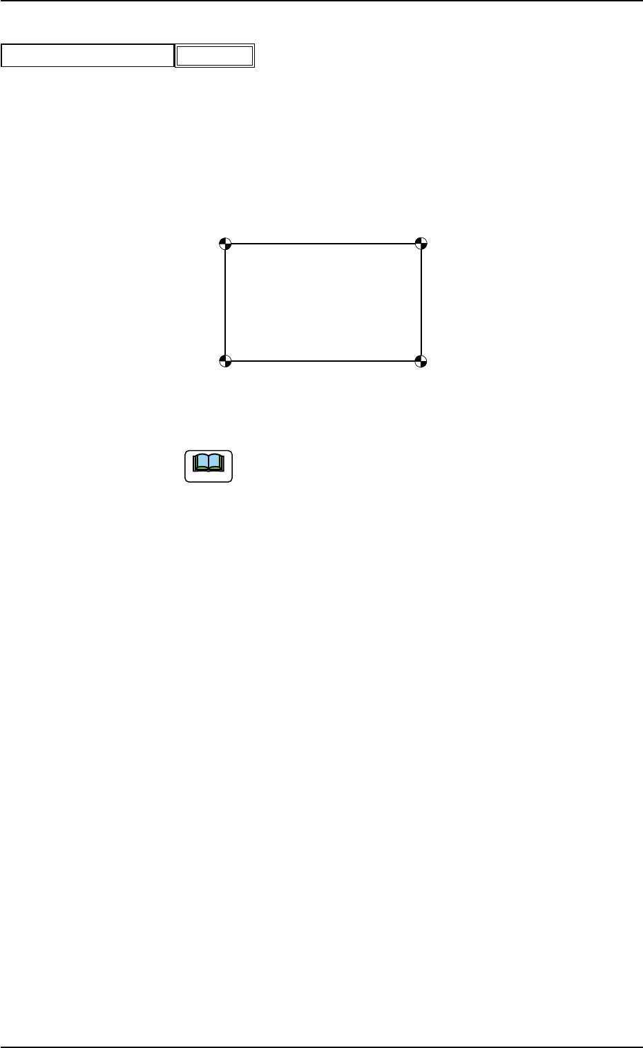
(A01_06) P.C.B. positioning reference
Displayed is a P.C.B. positioning reference point.
Rear Left : P.C.B.’s are positioned based on the rear left corners.
Front Left : P.C.B.’s are positioned based on the front left corners.
Front Right : P.C.B.’s are positioned based on the front right corners.
Rear Right : P.C.B.’s are positioned based on the rear right corners.
Fig. 3B21
The P.C.B. positioning reference must be changed when the
pattern program (prepared for the machine that requires a
different P.C.B. positioning reference) is used.
Front Ri
g
ht
Rear Right
Front Left
Rear Left
051 1-002 2-17 AIL01EDTP
2.3 Operation Data
P.C.B. positioning reference
Fig.3B20
Front Right
Note
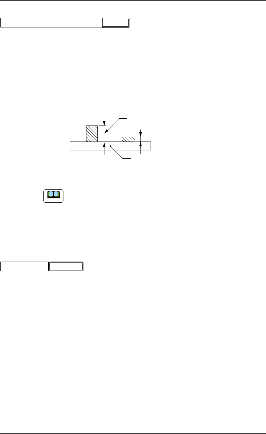
(A01_07) Pre-Placed component thickness
When some components are placed previously on a P.C.B. by the
input machine and transferred to the main machine, be sure to enter
the thickness of the tallest component of all in the text box.
Unit: mm
When components are not placed previously, set "00.000" (zero) in
the text box.
Data Input Range : 0.000 to 6.500
Fig. 3B23 State of Component Placement in Input Machine
(a) When components are placed previously and the main machine is
operated with "00.000" (zero) in this text box, some of the previously-
placed components may interfere with components to be placed
newly.
(b) It is advisable that placement data should be created such that shorter
components are placed before the tallest one.
(A01_08) Placement mode
Set "Placement" or "Pass" in the text box.
In normal cases, select "Placement".
When "Pass" is set in this text box and the pattern program data is
selected as current one, the vacuum pump and blower motors are
automatically turned off.
P.C.B.
Set this thickness in the text box.
051 1-003 2-18 AIL01EDTP
2.3 Operation Data
Placement
Placement mode
Fig. 3B24
00.000
Pre-Placed component thickness [mm]
Fig. 3B22
Note