3OM-1003-005.pdf - 第253页
3 .7 "Handling/Placement Data" T ab The corresponding tab sheet enables the operator to view the handling/ placement data. • Sheet Layout When the "Handling/Placement Data" tab is pressed in the "…
(14) [Nozzle Down Error (H)] Button
Each text box shows the number of errors in nozzle descending
level (H) for each individual nozzles.
(15) Component backtrack
Shown is the total number of component backtrack errors for each
individual nozzles.
(16) Component output error (Pickup error)
Shown is the total number of the output-error-caused compo-
nents (pickup errors) for each individual nozzles.
(17) Component output error (Others)
Shown is the total number of the output-error-caused compo-
nents (errors other than pickup ones) for each individual nozzles.
When one of the above buttons is pressed, the feeder No. with
the biggest parameter under the selected button is displayed in
the first line and feeder Nos. having the subsequent (second,
third, fourth, ...) biggest parameters follow. That is, parameters
are re-arranged in order of error counts (from the biggest to the
smallest ones), making it easy to analyze and improve produc-
tion rate.
When the [Head-Noz.] button is pressed, head-nozzle Nos. are
arranged in their initial order (order of head-nozzle Nos.).
*2 Vertical Scroll Bar
Up and down arrows are located at both ends of a scroll bar. The up
or the down arrow can be pressed to scroll up or down a tab sheet
to expose hidden parameters (data for the hidden head-nozzle Nos.).
*3 Horizontal Scroll Bar
Right and left arrows are located at both ends of a scroll bar. The
right or the left arrow can be pressed to scroll right or left a tab sheet
to expose hidden parameters (data for the hidden head-nozzle Nos.).
3.6 "Nozzle Management Data" Tab
0403-002 4-28 AIL01EDTP
Note
3.7 "Handling/Placement Data" Tab
The corresponding tab sheet enables the operator to view the handling/
placement data.
• Sheet Layout
When the "Handling/Placement Data" tab is pressed in the "Manage-
ment Data" window, the following tab sheet appears inside the window.
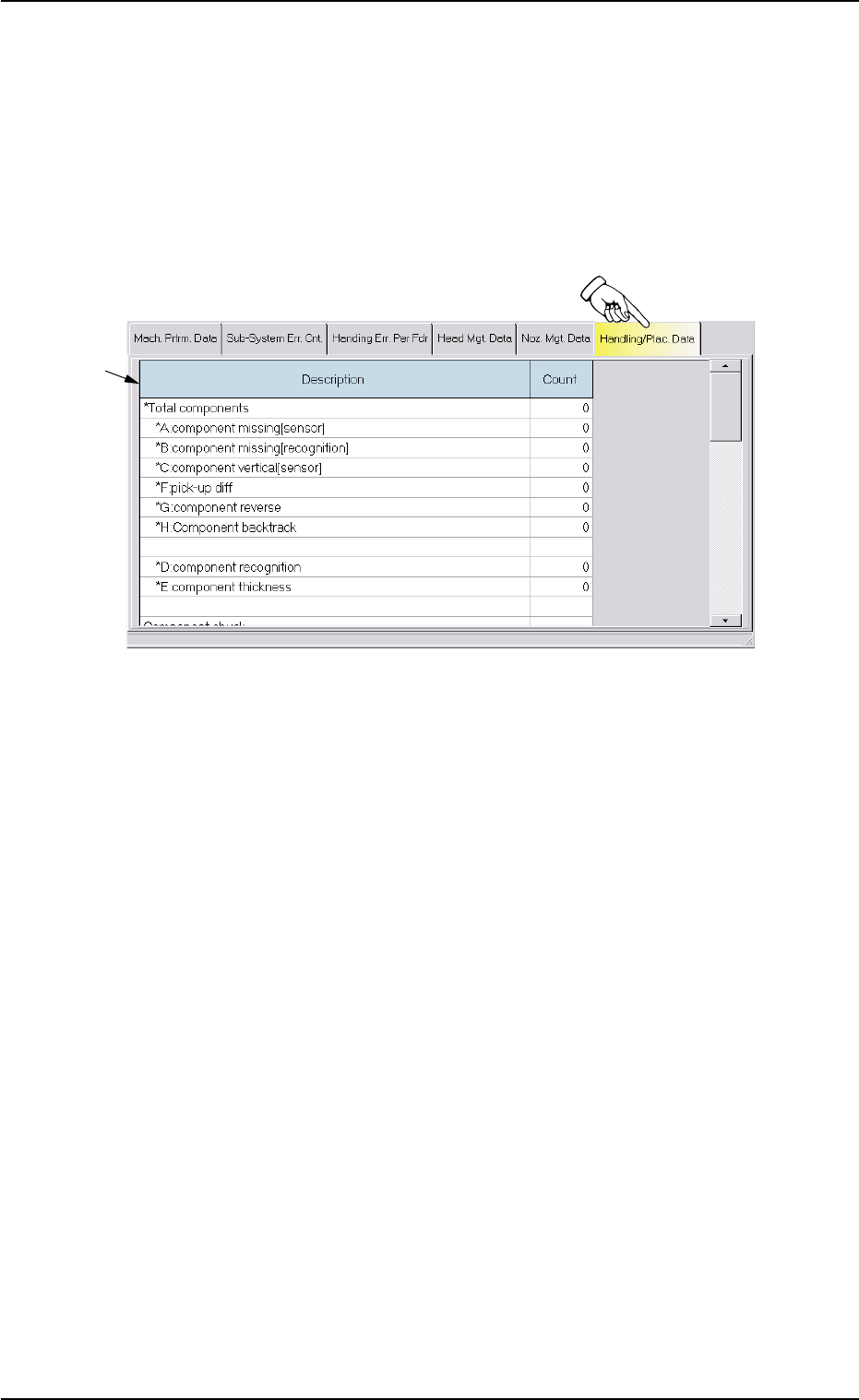
Fig. 3D14 "Handling/Placement Data" Tab Sheet
• Sheet Composition
*1 Description and Count
The following items are displayed.
(1) *Total components
The corresponding "Count" text box shows the number of com-
ponent picks.
*A: component missing [sensor]
The corresponding "Count" text box shows the number of miss-
ing components detected by the linear measure detection sen-
sor.
*B: component missing [recognition]
The corresponding "Count" text box shows the number of miss-
ing components detected through component recognition op-
eration.
*C: component vertical [sensor]
The corresponding "Count" text box shows the number of verti-
cal components detected by the linear measure detection sen-
sor.
*F: pick-up diff
The corresponding "Count" text box shows the number of "Pick-
Up Difference Errors" detected through recognition operation.
3.7 "Handling/Placement Data" Tab
*1
0403-002 4-29 AIL01EDTP
*G: component reverse
The corresponding "Count" text box shows the number of "Re-
versed Component Errors" detected through recognition opera-
tion.
*H: Component backtrack
Shown is the total number of component backtrack errors.
*D: component recognition
The corresponding "Count" text box shows the number of com-
ponents judged "NG" (No Good) through recognition operation.
*E: component thickness
The corresponding "Count" text box shows the number of errors
in component thickness detected by the linear measure detec-
tion sensor.
(2) Component chuck
[(*total comp.-(*A + *B + *C + *F + *G))/*Total comp. X100](%):
Value (%) determined by the following formula
(# of Picks - (Counts in *A + Counts in *B + Counts in *C + Counts
in *F + Counts in *G))/# of Picks x 100
(3) Component placement
[(*total comp.-(*A + *B + *C + *D + *E + *F + *G + *H))/*Total comp.
X100](%): Value (%) determined by the following formula
(# of Picks - (Counts in *A + Counts in *B + Counts in *C + Counts
in *D + Counts in *E + Counts in *F + Counts in *G + Counts in *H))/
# of Picks x 100
About Data Counting (Counting of "*A: component miss-
ing [sensor]" and "*B: component missing [recognition]"
(a) When the tape end detection function is used, a compo-
nent shortage alarm is issued after the tape end is de-
tected continuously 3 times.
When "Missing Component" is detected and a component
shortage error occurs after the alarm is issued, the last
chuck action is not added to the number of picks and the
number of chuck errors.
(b) When the tape end detection function is not used, the ma-
chine stops in an error condition according to the number
of times (the number of continuous component missing
errors to be counted to stop the machine in an error condi-
tion) set in the "1" text box of "Error process" in the "Con-
trol Data" tab sheet of the "Component Library" window. In
this case, the number of missing component errors is not
added to the number of picks and the number of chuck
errors.
3.7 "Handling/Placement Data" Tab
0403-002 4-30 AIL01EDTP
Note