3OM-1003-005.pdf - 第259页
(3) Passed P .C.B. The number of passed P .C.B.’s is counted when the machine is set in the "P ASS" mode. Counting is implemented when the P .C.B. transfer starts (when the P .C.B. on the X/Y table is transferr…
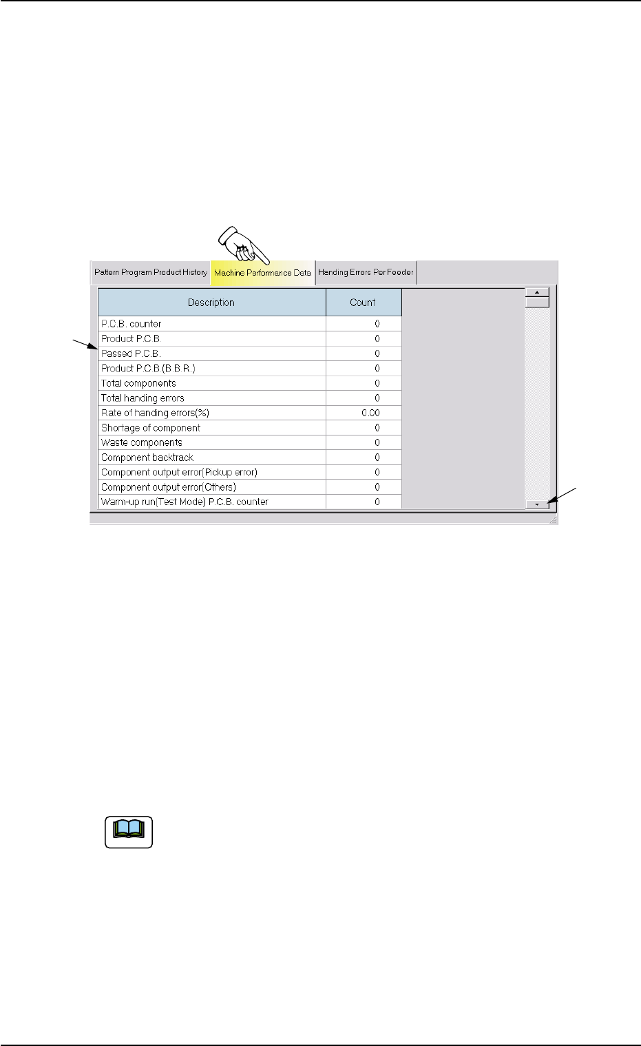
4.2 "Machine Performance Data" Tab
The corresponding tab sheet enables the operator to view the perfor-
mance data of the production model.
• Sheet Layout
When the "Machine Performance Data" tab is pressed in the "Pat-
tern Program Management Data" window, the following tab sheet ap-
pears inside the window.
Fig. 3D17 "Machine Performance Data" Tab Sheet
• Sheet Composition
*1 Items
The following items are displayed.
(1) P.C.B. counter
Shown is the number of produced P.C.B.’s.
Counting is implemented when the X/Y table is zeroed after com-
ponent placement operation (when a P.C.B. is finished).
When a particular pattern program is set several times as cur-
rent one, the sum total is computed.
(2) Product P.C.B.
The number of produced unit P.C.B.’s on multi-unit P.C.B. is
summed up. Counting is implemented when the X/Y table is ze
roed after component placement operation (when a unit is fin
ished).
When the unit P.C.B. B.B.R. detection function (option) is used,
defective unit P.C.B.'s are excluded.
4.2 "Machine Performance Data" Tab
0403-002 4-34 AIL01EDTP
*2
*1
Note
(3) Passed P.C.B.
The number of passed P.C.B.’s is counted when the machine is
set in the "PASS" mode.
Counting is implemented when the P.C.B. transfer starts (when
the P.C.B. on the X/Y table is transferred to the output conveyor).
(4) Product P.C.B. (B.B.R.)
Shown is the number of defective P.C.B.'s summed up when
the unit P.C.B. B.B.R. detection function (option) is used
(5) Total components
Shown is the number of picked components (the number of pick-
up operations).
(6) Total handling errors
Shown is the total number of component handling errors.
(7) Rate of handling errors (%)
Shown is the percentage of handling errors per total number of
picked components.
(8) Shortage of component
Shown is the total number of detected component shortage er-
rors.
(9) Waste components
Shown is the total number of components that were picked up
but not placed.
The indicated number of components represents the compo-
nents that were not placed due to a vertical component error
(sensor), a component recognition error, a component thick-
ness error, interrupted production, the detection of unit P.C.B.
(B.B.R.) (option), etc.
(10) Component backtrack
Shown is the total number of component backtrack errors.
(11) Component output error (Pickup error)
Shown is the total number of the output-error-caused compo-
nents (pickup errors).
(12) Component output error (Others)
Shown is the total number of output-error-caused components
(errors other than pickup ones).
4.2 "Machine Performance Data" Tab
051 1-003 4-35 AIL01EDTP
Note

(13) Warm-up run (Test Mode)
The data of the warm-up run (dry cycle) is counted.
P.C.B. counter
The number of P.C.B.’s is counted when the machine is oper-
ated under the following condition.
• "ENABLE" set for "TEST RUN" in "Run Mode" Tab Sheet ("OPN.
MODE" Window)
• "PCB XFR Err Det Disabled" Check Box Checked
(State in which no P.C.B. is put in and out)
Not Picked Counts
The number of non-picking/non-placement actions is counted
when the machine is operated under the following condition.
• "ENABLE" set for "TEST RUN" in "Run Mode" Tab Sheet ("OPN.
MODE" Window)
• "Handling/Place Disabled" or "Vacuum/Blower Disabled" Check
Box Checked
(14) P.C.B. process time
Shown is the total of the time required to finish a P.C.B.
4.2 "Machine Performance Data" Tab
0403-001 4-35-1 AIL01EDTP