3OM-1003-005.pdf - 第175页
4.3 "Placement Feeder Location" T ab 051 1-002 2-104 AIL01EDTP Allocation of Component ID (1) Select the "Feeder Carriage #" tab where a component ID should be allocated. (2) Select the feeder No. (Fd…
051 1-002 2-103 AIL01EDTP
4.3 "Placement Feeder Location" Tab
*8 [Link ID] Button
Link and root IDs are arranged side by side and displayed in the tree
(hierarchical) file system.
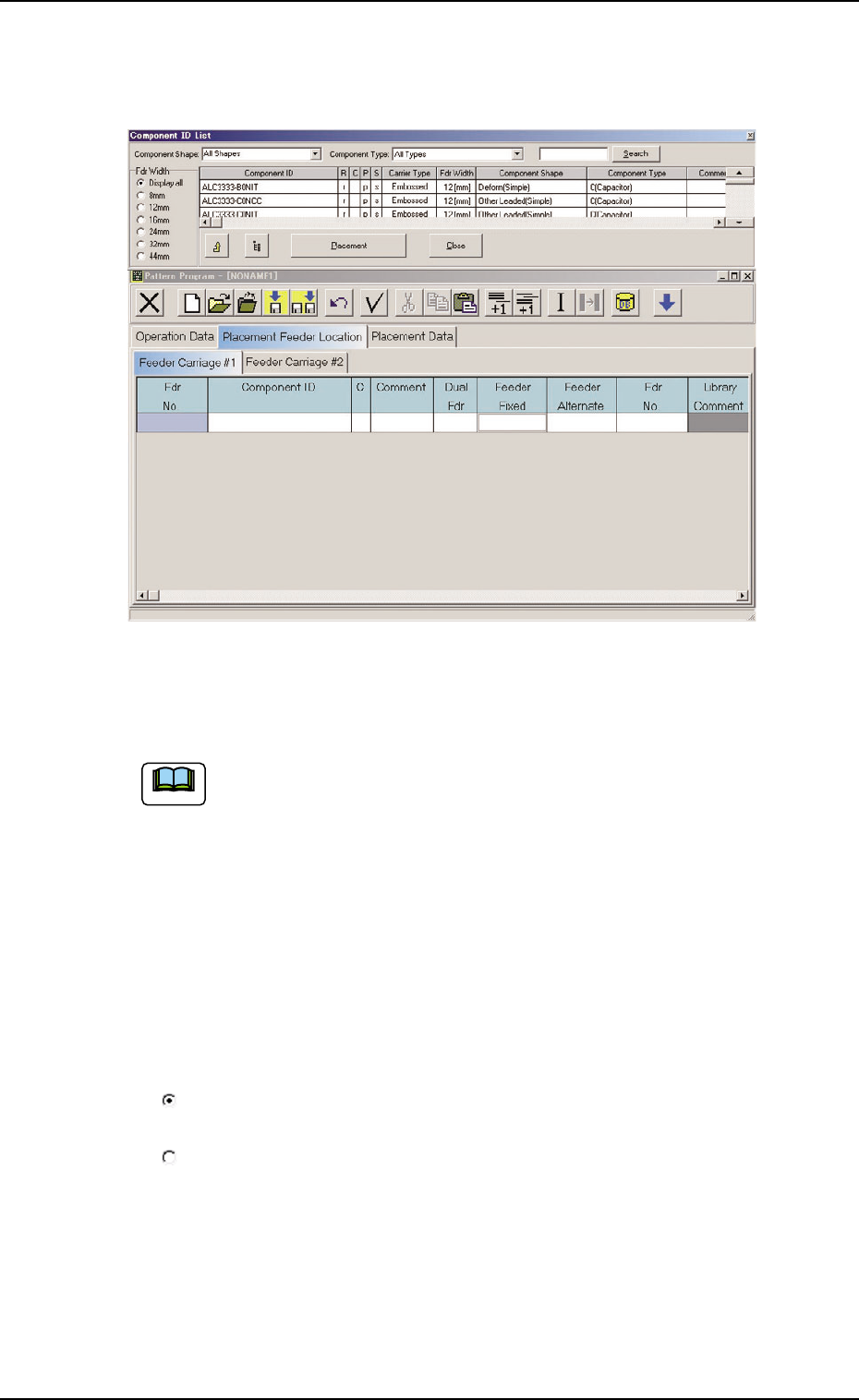
Fig. 3B166 Arrangement (Example) of "Component ID List" Window
• Operation Procedure
It is recommended to drag and drop the "Component ID List"
window at a place where it can be arranged for easier naviga-
tion as shown in Fig. 3B166.
Selection of Feeder Width
When several items (functions) are grouped and one of them must be
selected, option buttons are provided in front of the items, allowing you
to choose a single item (function) from a group of options.
A list of components related to the selected feeder width is displayed in
the "List of Component IDs" pane (*6).
Option Buttons
: A dot inside the circle indicates that the corresponding function is
selected.
: The corresponding function is not selected.
Turning on or off an option button
When a dot is not in an option button, it means that the item (function)
is not selected. When such an option button is pressed, a dot ap-
pears inside the circle, indicating that the item (function) is selected.
When an option button having a dot in the circle is pressed, the dot
disappears, indicating that the selection of the item (function) is can-
celed.
Note
4.3 "Placement Feeder Location" Tab
051 1-002 2-104 AIL01EDTP
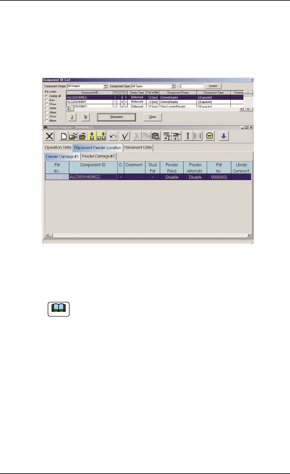
Allocation of Component ID
(1) Select the "Feeder Carriage #" tab where a component ID should
be allocated.
(2) Select the feeder No. (Fdr. No.) where a component ID should be
allocated.
The selected line (Fdr. No.) turns blue, indicating that it is selected.
Fig. 3B167
(3) Select the desired component ID to be allocated in the "Component
ID List" window.
Select the desired options from the "Component Shape" and
"Component Type" drop-down lists and the desired radio button
in the "Fdr Width" group box to determine the properties of the
component ID as the requirements to be fulfilled.
(4) Press the [Placement] button.
The selected component ID is allocated to the "Fdr No." line that
has turned blue.
Deletion of Allocated Component ID
(1) Select the desired "Feeder Carriage #" tab and the feeder No. (Fdr
No.) of the component to be deleted.
The selected line (Fdr. No.) turns blue, indicating that it is selected.
(2) Select the "Cut" icon on the toolbar. The selected feeder No. (Fdr
No.) is deleted and the subsequent feeder Nos. are shifted up.
Note
*1 *2
4.4 "Placement Data" Tab
0305-001 2-105 AIL01EDTP
4.4 "Placement Data" Tab
The "Placement Data" tab is provided with "U01 to Un" tabs and "P-
data" and "O-data" tabs. When a tab is selected, the corresponding tab
sheet appears.
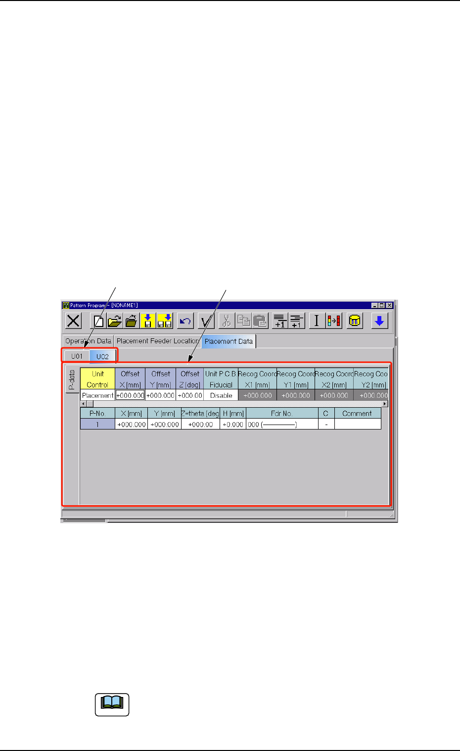
4.4.1 "U01" to "Un" Tabs
"U01" represents "Unit No. 01" and "n" in "Un" can be any number (01,
02, 03, ...). When the "Un" tab is pressed, the corresponding tab sheet
appears, enabling you to edit the parameters (placement data) of the
selected unit.
• Sheet Layout
When the [U01] tab is pressed after the [Placement Data] tab is se-
lected, the following tab sheet appears.
Fig. 3B168 "U01" Tab Sheet
• Sheet Composition
Each parameter is displayed or can be entered.
*1 [U01] to [Un] Tabs
These tabs are used to select a unit. When a tab is pressed, the
corresponding tab sheet appears and is related to the selected unit.
Refer to "• Operation Procedure" (described later) for the
detailed information on how to add or delete a unit.
Note