3OM-1003-005.pdf - 第83页
(A01_02) P .C.B. size X (horizontal) [mm], Y (vertical) [mm], and T (thickness) [mm] Set the dimensions of the P .C.B. to be produced. Unit: mm Fig. 3B1 1 When the P .C.B. has a cutout, the following dimensions must be e…
2.2 Pattern Program Name
To save a pattern program, it is required to give a name to the program.
Up to 32 characters (alphanumerics and marks) can be used.
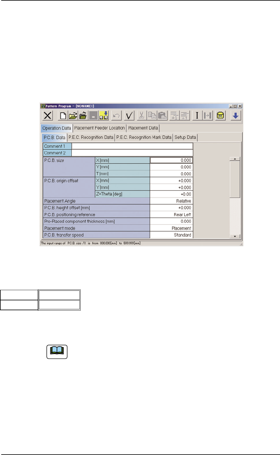
2.3 Operation Data
(A01) P.C.B. Data
Fig. 3B8 Edit Window (Example)
(A01_01) Comment 1, 2
Comments on the pattern program can be specified in these text boxes.
Up to 32 characters (alphanumerics and marks) can be used.
The performance of the machine is not affected by these comments. In
other words, it has nothing to do with or without these comments.
2.2 Pattern Program Name
051 1-002 2-13 AIL01EDTP
Fig. 3B9
Comment 1
Comment 2
Note
(A01_02) P.C.B. size
X (horizontal) [mm], Y (vertical) [mm], and T (thickness)
[mm]
Set the dimensions of the P.C.B. to be produced.
Unit: mm
Fig. 3B11
When the P.C.B. has a cutout, the following dimensions must
be entered.
Fig. 3B12
Data Input Range
TCM-X110J
X: 50 to 330 Y: 50 to 250 T: 0.5 to 5.0
TCM-X300S
• P.C.B. Origin Position : [to R460 mm]
X: 50 to 460 Y: 50 to 460 T: 0.5 to 5.0
• P.C.B. Origin Position : [to R510 mm]
X: 50 to 510 Y: 50 to 460 T: 0.5 to 5.0
• P.C.B. Origin Position : [to R560 mm]
X: 50 to 560 Y: 50 to 460 T: 0.5 to 5.0
• P.C.B. Origin Position : [to R610 mm]
X: 50 to 610 Y: 50 to 460 T: 0.5 to 5.0
330.000
250.000
1.600
X (Horizontal)[mm]
Y (Vertical)[mm]
T (Thickness)[mm]
Fig. 3B10
2.3 Operation Data
0305-001 2-14 AIL01EDTP
P.C.B.
P.C.B. Flow Direction
Y (Vertical)
X (Horizontal)
T (Thickness)
Y (Vertical)
X (Horizontal)
T (Thickness)
P.C.B.
P.C.B. Flow Direction
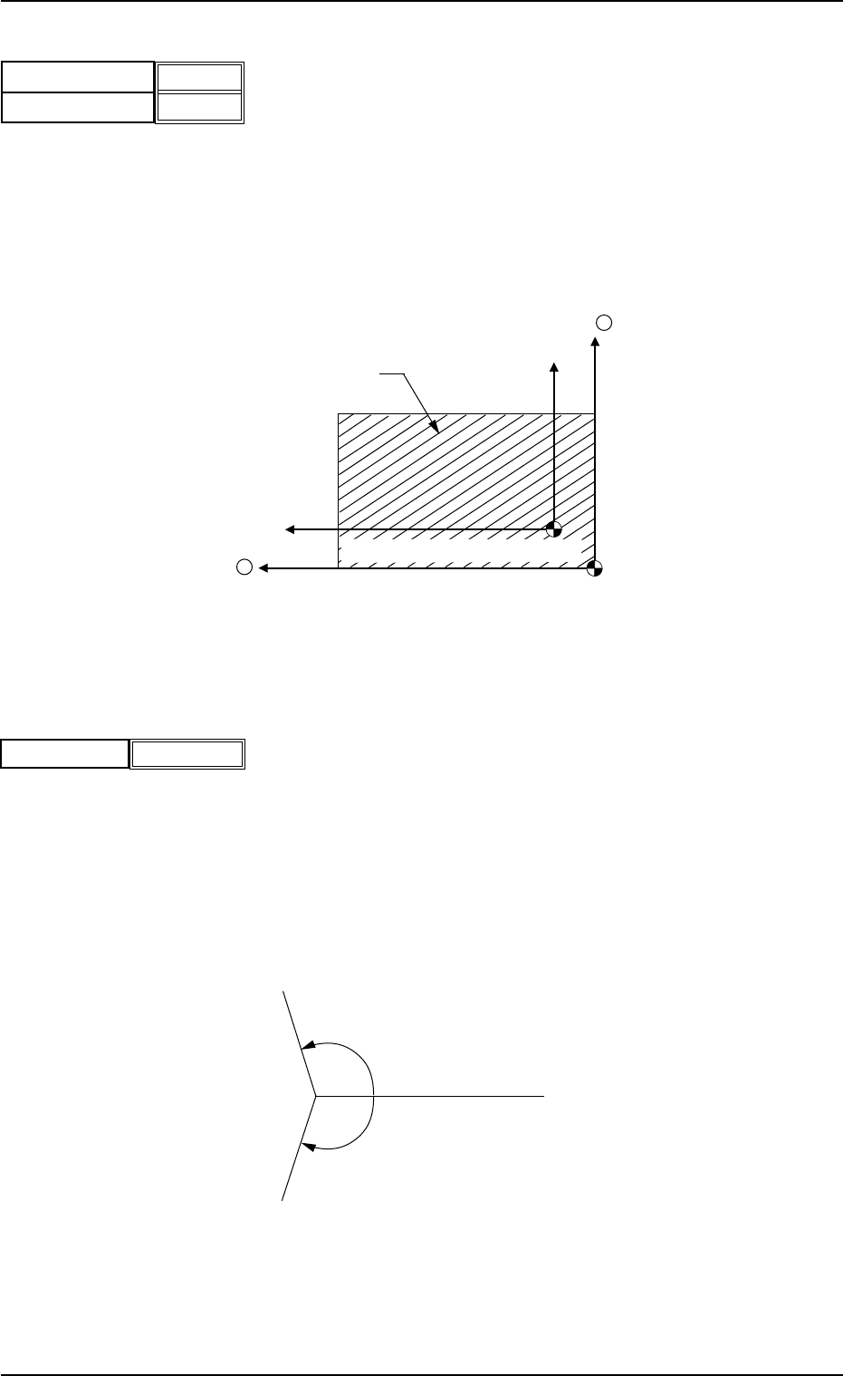
(A01_03) P.C.B. origin offset
X (horizontal) [mm] and Y (vertical) [mm]
Set the offset values to correct the difference between the placement
coordinate reference point (N
0
) and the P.C.B. origin (P
0
).
Unit: mm
"Plus" or "Minus" can be set in both X and Y coordinates in the direc-
tion of the correction.
Fig. 3B14 Example of "+" (Plus) Direction for Correction
Z=(Theta)[deg]
Set the offset value for component placement angle.
The set value is added to the "Z=theta" of all components in the place-
ment data (P data).
To correct the angle of component placement counterclockwise, a
parameter must be entered with a "+" (plus) sign. Put a "-" (minus)
sign to correct it clockwise.
Unit: degree
Fig. 3B16
P.C.B. Origin(P0)
X +
Y +
P.C.B.
Placement Coordinate Reference(N
0
)
Fig. 3B13
2.3 Operation Data
0305-001 2-15 AIL01EDTP
0°
+.°
-.°
X (horizontal)[mm]
Y (vertical)[mm]
+00.000
+00.000
Z=Theta [deg]
Fig. 3B15
+0.00