3OM-1003-005.pdf - 第310页
(1) "Nozzle Offset High Mag." T ab • Sheet Layout When the "Nozzle Offset High Mag." tab is pressed in the "Nozzle" tab sheet, the following tab sheet appears. Fig. 3E29 "Nozzle Offset …

• Sheet Composition
*1 "Noz Offset High Mag." Tab
When selected, the "Nozzle Offset High Mag." tab sheet appears.
*2 "Noz Offset Low Mag." Tab
When selected, the "Nozzle Offset Low Mag." tab sheet appears.
*3 "Noz Position" Tab
When selected, the "Nozzle Position" tab sheet appears.
*4 "Noz-L" Tab
When selected, the "Nozzle-L" tab sheet appears.
*5 "Noz-H" Tab
When selected, the "Nozzle-H" tab sheet appears.
*6 "Noz Detn L" Tab
When selected, the "Nozzle Detn L" tab sheet appears.
*7 "Noz Detn H" Tab
When selected, the "Nozzle Detn H" tab sheet appears.
3.2 "Device Offset" Tab
0403-001 5-29-1 AIL01EDTP
(1) "Nozzle Offset High Mag." Tab
• Sheet Layout
When the "Nozzle Offset High Mag." tab is pressed in the "Nozzle" tab
sheet, the following tab sheet appears.
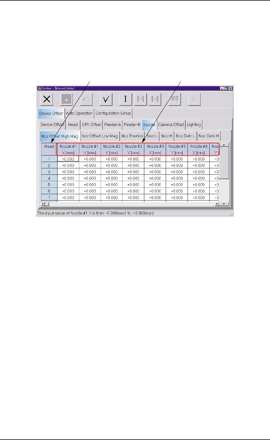
Fig. 3E29 "Nozzle Offset High Mag." Tab Sheet
• Sheet Composition
*1 Head
The head Nos. are displayed.
0403-002 5-30
AIL01EDTP
3.2 "Device Offset" Tab
*1
*2
*2 Nozzle #1 X [mm], Nozzle #1 Y [mm], Nozzle #2 X [mm], Nozzle
#2 Y [mm], Nozzle #3 X [mm], Nozzle #3 Y [mm], Nozzle #4 X
[mm], Nozzle #4 Y [mm], Nozzle #5 X [mm], Nozzle #5 Y [mm]
Each text box shows an offset value of nozzle position based on the
center of the component recognition camera (Camera #1 High Mag-
nification) at component recognition of each nozzle.
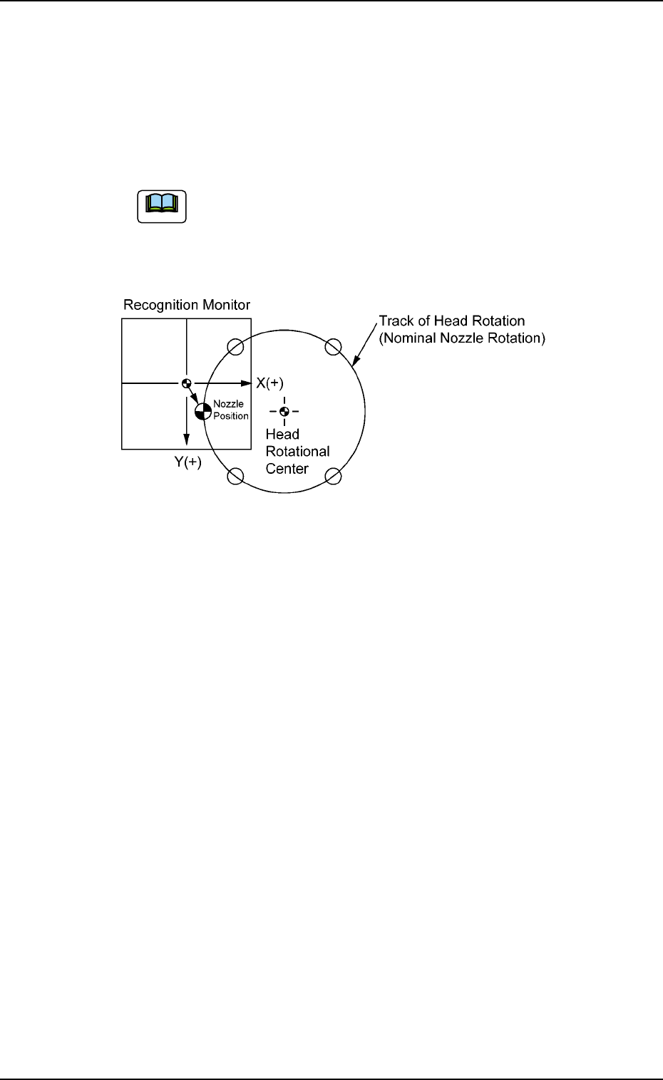
(a) These offset values are automatically calculated through
teaching operation.
(b) When a nozzle is located at the place shown below,
plus values are allocated for both X and Y.
Fig. 3E30
0305-001 5-31
AIL01EDTP
3.2 "Device Offset" Tab
Note